Construction & Working Drawings - Discussion
-
@rtbuild47 said:
I use LO all the time for Building Regulation and construction drawings and my only
gripe is that to define materials have to use colors or shades, when hatching would be so much more professional.artybuild
Hmm, I think the opposite. Hatching was developed to identify and define perameters of materials or scope, while SU and layout do this in a method to me that is more clear and direct. I would rather see CMU that looks like CMU rather than a cross hatch pattern that is referenced in a schedule telling you it is CMU.
-
@unknownuser said:
@rtbuild47 said:
I use LO all the time for Building Regulation and construction drawings and my only
gripe is that to define materials have to use colors or shades, when hatching would be so much more professional.artybuild
Hmm, I think the opposite. Hatching was developed to identify and define perameters of materials or scope, while SU and layout do this in a method to me that is more clear and direct. I would rather see CMU that looks like CMU rather than a cross hatch pattern that is referenced in a schedule telling you it is CMU.
I also suspect that hatching was a product of the times - plotters and printers that handled lines, and PCs that did the same.
-
@bmike said:
@unknownuser said:
@rtbuild47 said:
I use LO all the time for Building Regulation and construction drawings and my only
gripe is that to define materials have to use colors or shades, when hatching would be so much more professional.artybuild
Hmm, I think the opposite. Hatching was developed to identify and define perameters of materials or scope, while SU and layout do this in a method to me that is more clear and direct. I would rather see CMU that looks like CMU rather than a cross hatch pattern that is referenced in a schedule telling you it is CMU.
I also suspect that hatching was a product of the times - plotters and printers that handled lines, and PCs that did the same.
Actually those plotters and printers were the hand and pencil days. Ouch I'm getting old. I graduated architectural school in 1987, so hand drawing was still the main course, with ACAD just really starting to move in the industry.
-
@unknownuser said:
@bmike said:
@unknownuser said:
@rtbuild47 said:
I use LO all the time for Building Regulation and construction drawings and my only
gripe is that to define materials have to use colors or shades, when hatching would be so much more professional.artybuild
Hmm, I think the opposite. Hatching was developed to identify and define perameters of materials or scope, while SU and layout do this in a method to me that is more clear and direct. I would rather see CMU that looks like CMU rather than a cross hatch pattern that is referenced in a schedule telling you it is CMU.
I also suspect that hatching was a product of the times - plotters and printers that handled lines, and PCs that did the same.
Actually those plotters and printers were the hand and pencil days. Ouch I'm getting old. I graduated architectural school in 1987, so hand drawing was still the main course, with ACAD just really starting to move in the industry.
for sure. i was on the transition period when i dropped out. school was leaning towards a paperless studio for the 3rd year grads, but the first 2 years did a mix of traditional modeling, drawing, 3d, and bullshitting, i mean, critiquing. my prof in school was aghast that i wanted to learn autocad. guess he didn't have to work to put himself through school...
prior to grad school i came from an art school with a renaissance style traditional foundation program - so lots of life drawing - both human figure (i was marginal at it) and from observation - still life, landscape, architecture, etc.
lots of emphasis in design and painting coursework on sketching. i still have alot of my sketchbooks. flip through them every now and again... -
Mike, where did you go to school. Sounds a lot like my school - RISD.
-
@unknownuser said:
Mike, where did you go to school. Sounds a lot like my school - RISD.
Cleveland Institute of Art, BFA Sculpture, but I spent time in ID, Graphics, and lots of time working for carpenters and woodworkers.
Then to Columbia for Grad school in Architecture. Burned out after a year. Too much $$$$ for living in the city and going to school, and lots of folks who didn't seem to care about the art of actually building...
Had a good friend go to RISD for furniture. This would have been in mid 90s. Spent some time there hanging out, fun town. Will be there in 2 weeks visiting and engineer I work with and doing some warranty research on a project I designed a few years ago.
Also know a prof down at RISD via some artists I worked for as an assistant in NYC and a by way of a project that I worked on in Jamestown.
Small world.
-
@unknownuser said:
@rtbuild47 said:
I use LO all the time for Building Regulation and construction drawings and my only
gripe is that to define materials have to use colors or shades, when hatching would be so much more professional.artybuild
Hmm, I think the opposite. Hatching was developed to identify and define perameters of materials or scope, while SU and layout do this in a method to me that is more clear and direct. I would rather see CMU that looks like CMU rather than a cross hatch pattern that is referenced in a schedule telling you it is CMU.
Yeah, but in office work there is such a thing as standardization and efficiency. Hatches developed over time to have the consistent look and are easily identified (basic ones like wood, conc., earth anyway). And, of course it's something when done by hand you need the interns to learn, so it has to be easily defined and copied. It doesn't take an artist.
Nowadays we don't really want the "make-work"-let the computer do it. So eventually someone who has developed some nice detail textures will lead the way forward and set the standard.

-
@pbacot said:
@unknownuser said:
@rtbuild47 said:
I use LO all the time for Building Regulation and construction drawings and my only
gripe is that to define materials have to use colors or shades, when hatching would be so much more professional.artybuild
Hmm, I think the opposite. Hatching was developed to identify and define perameters of materials or scope, while SU and layout do this in a method to me that is more clear and direct. I would rather see CMU that looks like CMU rather than a cross hatch pattern that is referenced in a schedule telling you it is CMU.
Yeah, but in office work there is such a thing as standardization and efficiency. Hatches developed over time to have the consistent look and are easily identified (basic ones like wood, conc., earth anyway). And, of course it's something when done by hand you need the interns to learn, so it has to be easily defined and copied. It doesn't take an artist.
Nowadays we don't really want the "make-work"-let the computer do it. So eventually someone who has developed some nice detail textures will lead the way forward and set the standard.

Man I hope not. I think the beauty of SU textures is they look like real materials. They are not a hatch pattern, and are immediately recognized by all the contractors and laborers. Hatches are a cryptic way to depict materials, that are hopefully going to be gone by the way side. I get a lot of positive feedback on my details, especially from the Spanish speaking work force. In many cases, even the text isn't necessary.....a picture is worth a thousand words. Not sur you can say the same for a hatch pattern.
-
@unknownuser said:
Man I hope not. I think the beauty of SU textures is they look like real materials. They are not a hatch pattern, and are immediately recognized by all the contractors and laborers. Hatches are a cryptic way to depict materials, that are hopefully going to be gone by the way side. I get a lot of positive feedback on my details, especially from the Spanish speaking work force. In many cases, even the text isn't necessary.....a picture is worth a thousand words. Not sur you can say the same for a hatch pattern.
+!!!! on this. Absolutely. At some point our machines will be fast enough and the reproduction quality of prints good and cheap enough to build virtually in the computer with 'real' materials. We are almost there...
I get similar comments when I send off sketches or details, even by using 'simplified' textures and image placement. Makes a whole lot of sense for a foundation contractor to see grey / stone colored materials with steel popping out than some sort of hatch pattern. And I'm not going using as realistic as an approach as Sonder...
-
What do you hope not, Nick? Or you hope it is never standardized?
You mean each of us must create his or her own textures and these will always be recognizable by all, even neophytes?
I was hoping your pattern library would be available ($)
 . (Though I am far from doing such details myself, this might get me there sooner).
 -
@pbacot said:
What do you hope not, Nick? Or you hope it is never standardized?
You mean each of us must create his or her own textures and these will always be recognizable by all, even neophytes?
I was hoping your pattern library would be available ($)
 . (Though I am far from doing such details myself, this might get me there sooner).
My thought is that a material image (photographic) is more telling than a hatch pattern used to define a given material. I don't think there is a need to standardize images used in defining materials. Concrete can look like concrete in many different images. What I love about SU is the customization allowed by the individual user. We are not bound by standards like this anymore.
Using concrete as an example, just search Google images and you will see hundreds of images of concrete. Most all would clearly be seen as concrete given the context of application to a given foundation model/section/detail. There is no need for a standard pattern any more. I would hate to go back to that, so I really hope that is not something Trimble deems necessary for either SU or LO. I would much rather the focus be placed on getting us even further beyond what has been the industry standard.
-
@bmike said:
@unknownuser said:
Mike, where did you go to school. Sounds a lot like my school - RISD.
Cleveland Institute of Art, BFA Sculpture, but I spent time in ID, Graphics, and lots of time working for carpenters and woodworkers.
Then to Columbia for Grad school in Architecture. Burned out after a year. Too much $$$$ for living in the city and going to school, and lots of folks who didn't seem to care about the art of actually building...
Had a good friend go to RISD for furniture. This would have been in mid 90s. Spent some time there hanging out, fun town. Will be there in 2 weeks visiting and engineer I work with and doing some warranty research on a project I designed a few years ago.
Also know a prof down at RISD via some artists I worked for as an assistant in NYC and a by way of a project that I worked on in Jamestown.
Small world.
I know, crazy. I see you are in Vermont. I went to Kimball Union Academy near White River Junction.
-
@pbacot said:
What do you hope not, Nick? Or you hope it is never standardized?
You mean each of us must create his or her own textures and these will always be recognizable by all, even neophytes?
I was hoping your pattern library would be available ($)
 . (Though I am far from doing such details myself, this might get me there sooner).
To hell with the neophytes! (Ok just kidding, well sort of) I think simple hatch patterns will always have a place in architectural drawing. I like to just remove all the color from materials (will someone write me a plug in to change them back and forth from color to monochrome) What I want is copies of everybodies scrapbooks. How come there is no scrapbook warehouse ? (yes I'm lazy)
-
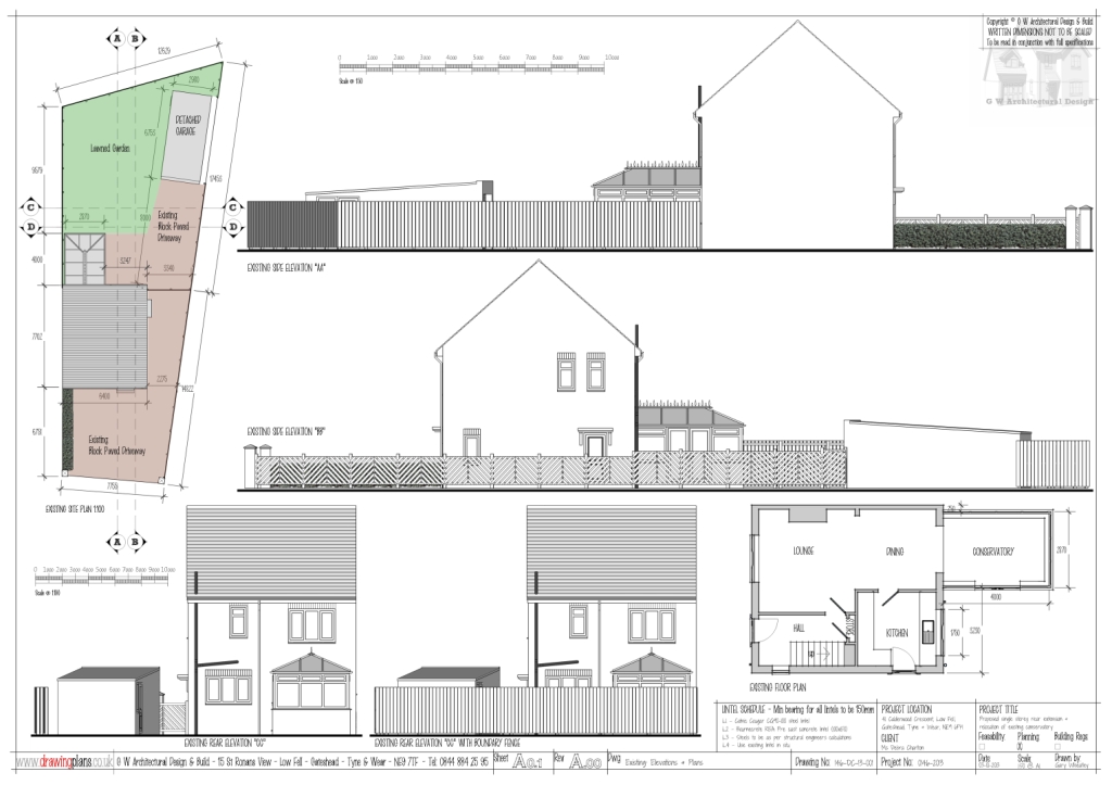
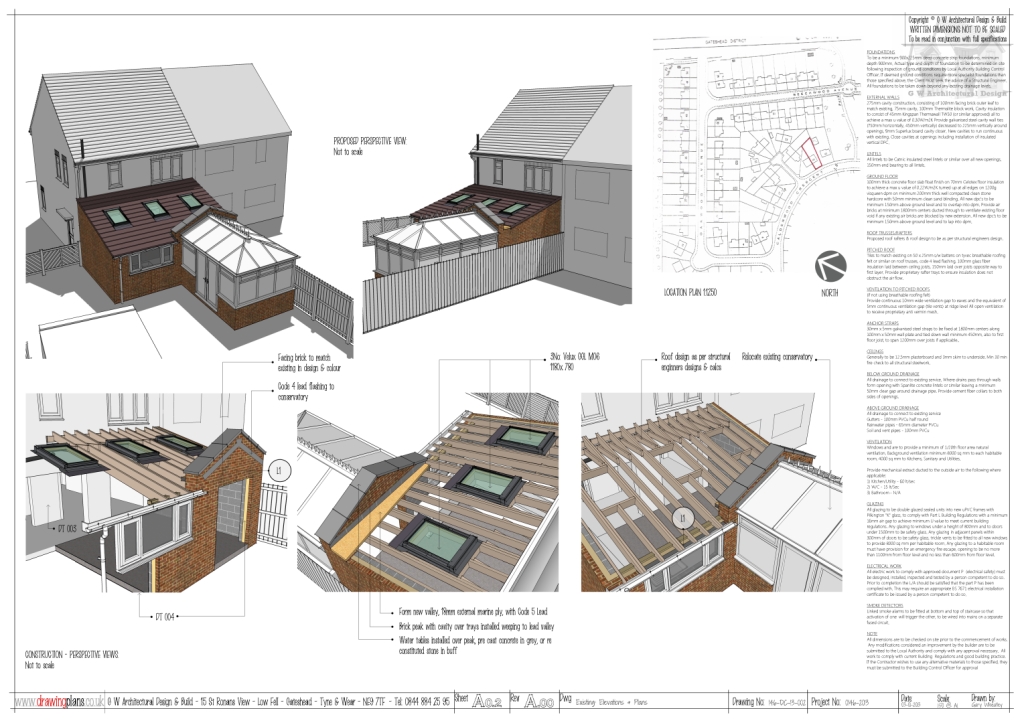
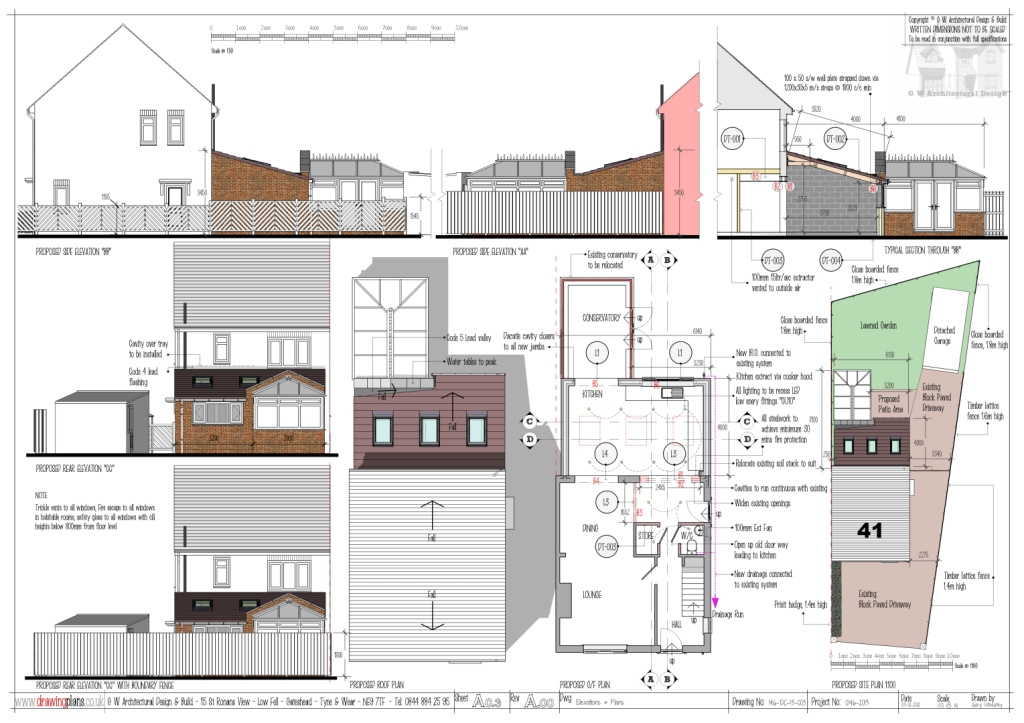
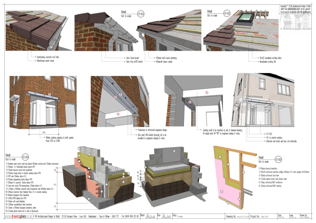
A long while since my last post. Here is the last job I did using only Sketchup & Layout from start to finish. I have only done a few jobs solely in SU LO, as most of my work consists of AutoCAD in one form or another. But I'm trying to avoid it as much as possible now.
One big help was making groups from slices. I saw this in one of Nick Sonders videos. I don't know how I missed that one in the past??? Also a good tip from Nick was try and do as little in LO as possible, basic text & line work etc. I think maybe this is where I was getting frustrated a bit!!! Trying to do to much in LO...?
A big thanks to Nick as his videos really are a help.
The job below is just a basic single storey extension (UK) There is more info on there "graphically" than I would normally supply in a set of AutoCAD plans, hence the time involved is also greater than I would normally take. I need to stop messing about and be more productive

Gaz...


-
Very nice work!
-
many compliments very well done work
-
YES. This looks very advanced, even if you feel you spending too much time. (You're shaming the competition.)
-
How the height dimensions are done in Layout?
-
@zx10r_gaz said:
The job below is just a basic single storey extension (UK) There is more info on there "graphically" than I would normally supply in a set of AutoCAD plans, hence the time involved is also greater than I would normally take. I need to stop messing about and be more productive

Gaz...
[attachment=3:ckktjyo7]<!-- ia3 -->A01-1024.jpg<!-- ia3 -->[/attachment:ckktjyo7]
I can't believe how much scaled information you can get on a sheet. very efficient. and yet still very attractive.
-
@unknownuser said:
I can't believe how much scaled information you can get on a sheet. very efficient. and yet still very attractive.
Krisidious,
All drawings are on A1 size media. This is:841 x 594mm or 33.1" x 23.4". All 2D scales are 1:50, or 1:100 if there is not quite enough room.
Gaz...
Advertisement


