Helix / Spiral With Increasing Pitch
-
I'm new to Sketchup ... only using it 3-4 months.
I need to draw parts of a plastics extruder screw.
These screws are somewhat similar to an auger but usually incorporate some more complicated features such mixers, wave roots, etc, etc.
One feature sometimes is a "barrier flited section". A seconday, more narrow, flite with slightly less height will be between the primary flites for possibly 6-10 turns.
This secondary flite also may have a progressive lead. It's lead / pitch smoothly changes with the flite's turns.
My question: Is there a fairly easy way to increase the pitch /lead of something like this ... which is mostly a helix or spiral with a profile?
Plugins like screw and helix, drawhelix, etc, are great but have no input for this type of feature.Keith
-
I don't know of a plugin that will do it but it's an interesting idea.
I can think of a couple of ways to do something that might get you close. It won't be perfect but it might get you what you need.
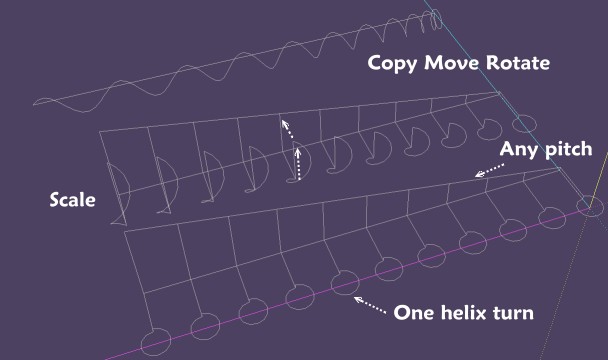
In the example above I made a single turn helix, the first turn at the bottom, and then I copied it up to the next turn and scaled that turn slightly. Copy, Scale, Copy, Scale...
The other option to get the same result is to make multiple single turn helices and move them end to end. It won't be perfect because the pitch only changes with every turn but if the pitch change isn't dramatic, it won't be visible. You aren't making engineering or manufacturing drawings out of these, are you?
-
You could try Sketchy FFD.
http://sketchucation.com/forums/viewtopic.php?t=6029#p36127
Could you post a pic of what you want?

-
Thanks guys for the replies. I am looking into the suggestions.
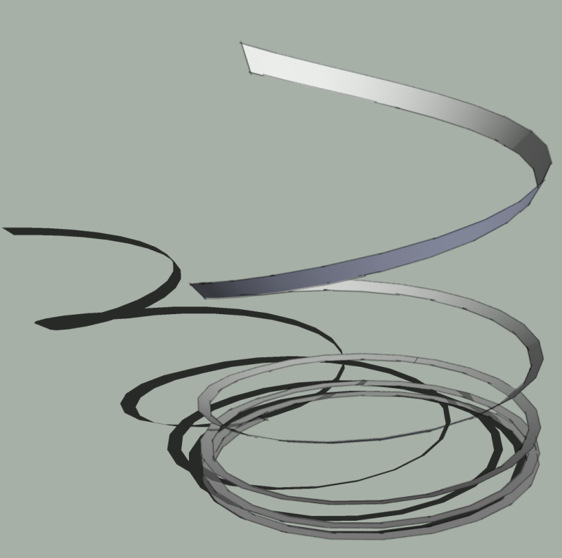
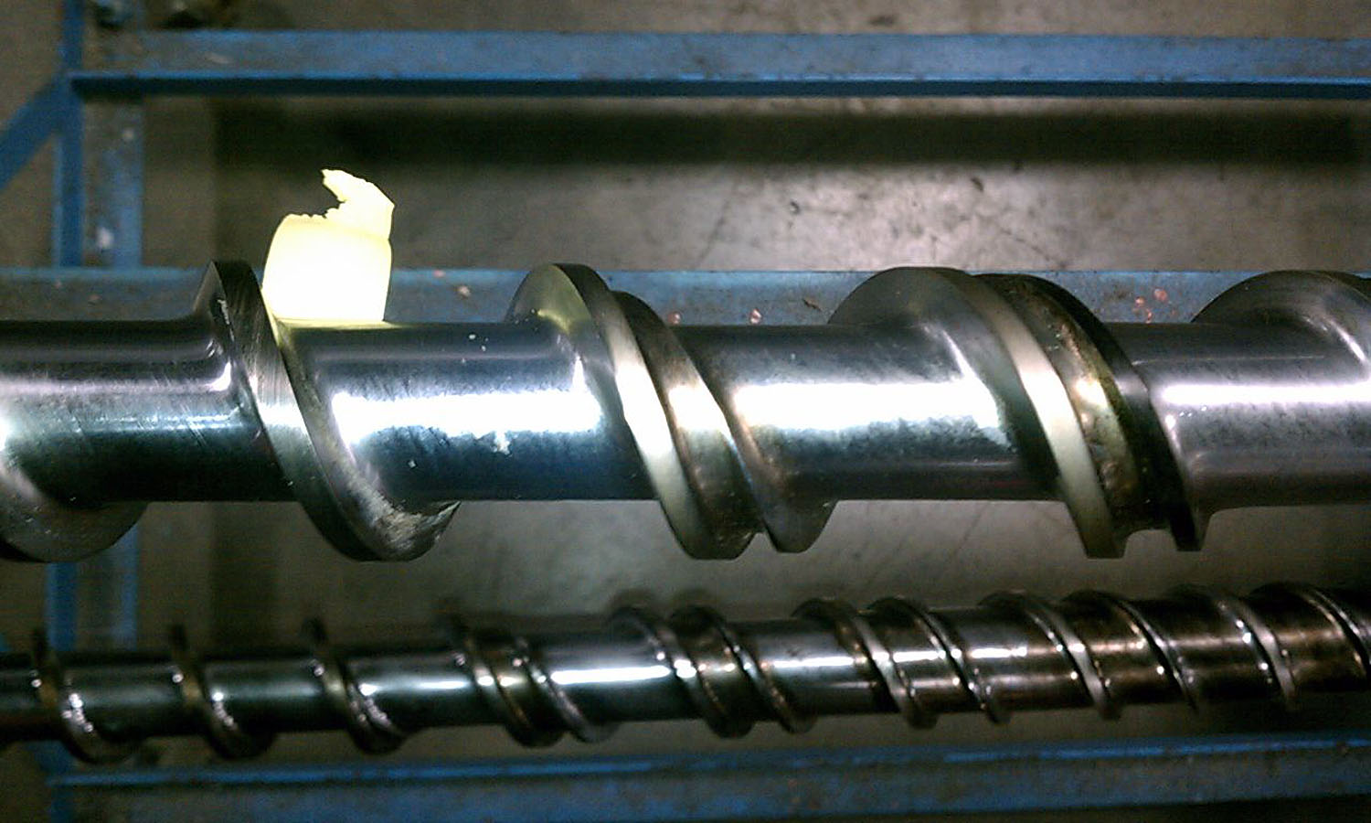
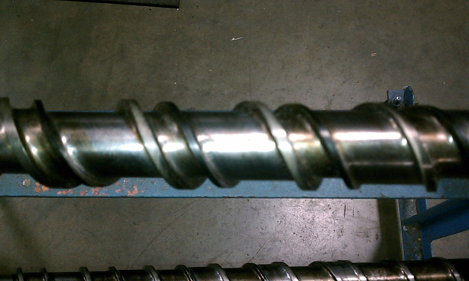
The models will be used to represent extrusion screws but the models will be redrawn in autocad for actual manufacturing. If I can more or less get a good visualization with most of the dimensioning in Sketchup the next stage can be handled by a design engineer. These models I guess are more or less field drawings but I'd like them to be a good representation. I usually do some in 3d iso and then turn some into parallel projection. I've attached 2 pics of the actual parts ... though not the best quality, and a drawing to some the idea of the incremental flite lead / pitch.Keith
-
Maybe like this with some variations?
-
A good youtube presentation and tutorial.
Though ... my main question I guess is creating a secondary flute that as it turns and progresses along the screw shaft it smoothly increases pitch or lead. An example might be it increasing 0.150" with each turn ... but doing it in a manner that has no noticeable stop/start points during the pitch increments.I am going to play around with all the suggestions I've received.
I was wondering if someone has had to do this incremental pitch several times and
had settled on a way to accomplish it. -
One turn helix was made with Draw Helix 14 by Jim
Maybe something like this

Does this sufficient, not enough progressive? Too discrete ?Maybe you can see also Grow by Tig from just one inclined segment!

-
@dkw1118 said:
I've attached 2 pics of the actual parts ...
maybe overthinking it some..
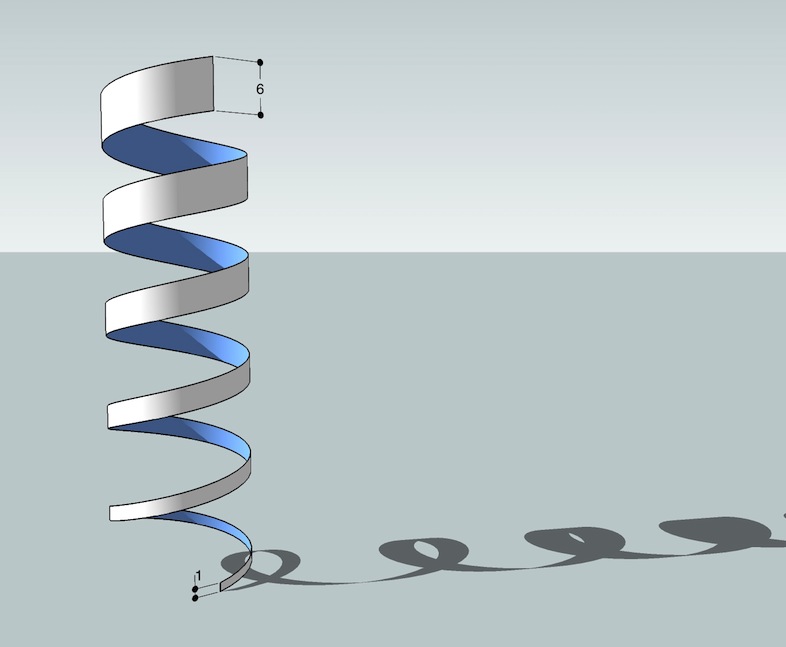
those parts look like they're made using two standard helixes and not a spiral whose pitch increases as you go around (i.e.- the things the fellas are drawing in this thread)for this pic, i drew a helix then copy/moved it vertically... selected the second helix and scaled it vertically.. [then skinned it using curviloft]
-
After seeing your drawing, Keith, I would agree with Jeff. I think he's hit the nail on the head.
-
I guess looks can be deceiving.
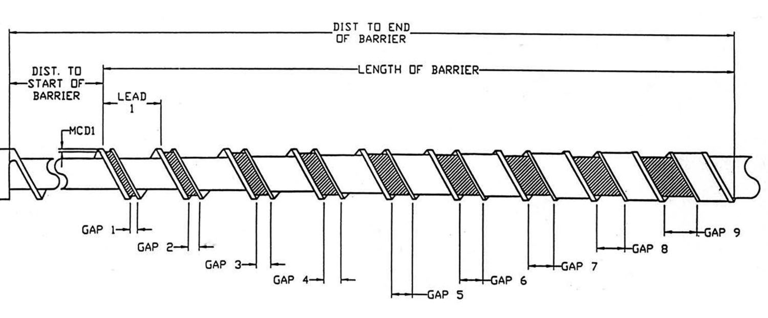
Here's how it goes:(1) The primary flite has a lead of 1.75" for a distance of 12.25" then transitions in to a 2.5" lead within a 2.875" span.
(2) The primary flite lead remains constant again at 2.5" for a length of 16.25" within what is called a barrier section.
(3) The secondary (thinner flite) begins in the barrier section and it's lead is increasing by 0.150" per turn. It ends at the the end of the barrier section just before it "catches up" with the primary flite.
(4) The primary flite then transistions back to a 1.75" lead for 13.5".
This is pretty normal for extruder screws with barrier sections. This particular screw is small in diameter at only 45mm. Most range between 3.5" to 6" o.d., 8" not uncommon, and up to 15"+. There are many variations on these barrier sections but this probably should give you the basic idea.
Keith
-
In any case, it would be in your best interest to model this scaled up, because those incremental distances are very small and could create closure problems on surfaces.
-
Thanks all for your comments. Hopefully in a couple of days I'll get a chance to dedicate more time to your suggestions.
Keith
-
@dkw1118 said:
I guess looks can be deceiving.
Here's how it goes:
.............
Keithhey Keith,
i don't know if those dimensions came from the pics you posted but if these screws do in fact have a variable pitch, i'm sure a ruby could be made to accommodate the shape..i don't know ruby so i messed around with a dynamic component.. the problem is, DCs are very limited so i was only able to get the varying helix with guide points..
as the attached dc is now, there is no input for start and end pitch.. it's basically wrapping a 1/4 circle around a 36 segment cylinder (i.e.- going from 0º start pitch to 90º end pitch)..
you'd then have to connect the dots manually (or maybe use a ruby?) to get the actual lines in there..
if you think it'd be helpful, i could mess around with it some more to get start/end pitch functionality..
here's the .skp:
-
And why not draw some remarquable points following the helix path (each quarter), thean draw a bezier spline (FSpline) from Fredo6 with numerous points on the spline on theses quarters?
Like this you will have a soft transition between each changment of pitch!
Hello! It looks like you're interested in this conversation, but you don't have an account yet.
Getting fed up of having to scroll through the same posts each visit? When you register for an account, you'll always come back to exactly where you were before, and choose to be notified of new replies (either via email, or push notification). You'll also be able to save bookmarks and upvote posts to show your appreciation to other community members.
With your input, this post could be even better 💗
Register Login


Advertisement