[Plugin] Hole Punching Tool
-
excellent plugin, thank you very much.
A consultation is possible that the contextual menu only is activated, when you right click the mouse on a component.? -
@jorge2011 said:
excellent plugin, thank you very much.
A consultation is possible that the contextual menu only is activated, when you right click the mouse on a component.?Most submenu items are only active [i.e. not gray] when there is an appropriate selection [e.g. cutting-component[s] that are not punched or ones that are punched activate different options - because you can't punch with one that's already punched and you can't unpunch one that's not been punched!].
See this post http://forums.sketchucation.com/viewtopic.php?p=350006#p350006 - as well as the notes on the main download page... -
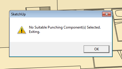
So Tig. . .I keep getting this. . .what constitutes a "suitable" component?
Not properly attired? No shoes? no shirt? no service?

-
A 'suitable' component has to be made to glue to a face and cut a hole in that face [z/blue axis out of the face] - that's a standard Sketchup thing. Of course it also has to have been glued onto a face! You can easily make a component with those behaviors, or by editing one later etc - imported hole-cutting window and door components are premade to have this gluing/cutting behavior.
The Hole-PUNCHING tool can then extend the component instance's hole-cutting behavior so that it continues its hole in the wall's outer face through to the inner face of the wall, with reveals etc...
Select one or more glued/cutting component-instances and run the tool and they will punch right through the wall.
If a wall is thicker than the maximum default of 20"/500mm you can reset it in a dialog, however all walls thinner that the limit will punch correctly, so adjusting this is rarely needed... -
Great. . .As a duly authorized green-badged Sketchucator deputy-- it shames me to say I have always sucked at hole-cutting components. I gotta get batter at that sort of thing.

Thks for the reply.
-
Got if fixed.
Thx,
D
-
thank you for the tool, sir.
-
hi,
i have a problem with this model with a component i made.
planned to use Hole Punching Tool on the component.
but i couldn't make it work well.
is there something that i missed here?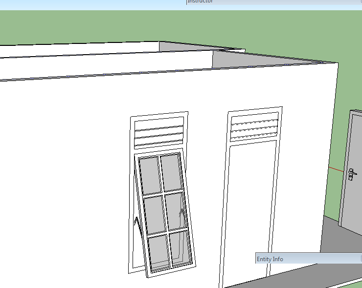
-
Irwan
For any component to be able to 'cut' a hole it needs a looped outline that is on the plane of the face onto to which it is 'glued'.
Examining your component#1 I see that it is an assembly of subcomponents - which in itself is not a bad thing... BUT as a result of that there is no continuous loop of edges on the face-plane; so although it 'glues' to a face, it doesn't 'cut' it, and because it doesn't cut it then it doesn't 'punch' through to any inner face either.
BUT don't despair - it's easy to fix this.You can edit the component whilst it is on the wall, select-all and move everything back a few mm so that the front-face of the window-frame are on the wall-face with the axes.
Now it will cut its hole in the face it is glued onto, and then it can also punch through to the inner leaf...Alternatively, IF you really want your window-frame to project slightly in front of the wall-face like you have made it currently, then you must add an extra set of lines around the outside of the frame so that there is then a rectangle on the wall's face that will be recognized as the 'cutting-loop' [and also form any 'punching-loop' too]. If you draw such a rectangle inside the component as raw geometry you will find it will make a face, which you don't want - select that face only and delete it, but leave the four edges in place to define the 'cutting-loop'...
-
@tig said:
Irwan
You can edit the component whilst it is on the wall, select-all and move everything back a few mm so that the front-face of the window-frame are on the wall-face with the axes.
Now it will cut its hole in the face it is glued onto, and then it can also punch through to the inner leaf...does that mean i don't have to explode the window so the window frame become able to provide looped outline?
actually, i've changed that to be a bit further off surface. after reading other post about HPT. if i'm not mistaken there are posts with "1 mm shift above surface"?
so, i don't have to shift the window above the surface about 1 mm?
here is the actual component i made. without that shift above the surface.
Jendela 6 Kaca Vent.skp
i'll see if i could understand the instruction, sir. i'll play with the model again. -
greetings, sir.
the HPT works well when the window component exploded and applied HPT on the window's frame.
selecting all components of the window and move them altogether, moves the cut along with them.
but when HPT applied, some components were shifted backward from the wall.
-
Irwan
You do NOT need to explode subcomponents !
BUT there must be a continuous closed loop of edges on the face-plane for Sketchup to find something to make the 'cut-hole' with...
This can be a loop within a subcomponent OR a separate loop draw within the assembled parts.
So you must EITHER move the assembled parts inside the component-edit so that there is then a loop of edges on the face-plane OR you must add a new loop of edges [in your case a rectangle] into the component's contents that is on the face-plane [deleting the face that gets added and keeping the edges].
Using one of these methods means that a loop is detected when you glue the instance onto a face and therefore a hole is cut in the face [then if desired that loop can be used to also 'punch' the whole wall later on].Why try to shift the component off the surface 1mm ?
I think you have confused an issue with 'projecting sills'...
If a window has 'horns' on its sills so that they project sideways on the face-plane then these will also 'cut' the face [like an inverted 'T' shape].
This is unimportant IF you are never going to 'punch' it.
BUT if you do a punch with such a component then it will make an unexpected hole through the wall because the sill's ends will punch through too!
To avoid this issue you simply need to adjust the windows sill geometry so that any parts of it that are on the wall face that are now offset by say 1mm inf front of the face, and adjust the remainder of the 'cutting-loop' to suit the required 'hole'.
Then the main rectangle of the window that you want to make the cut does so, and later any related punched reveals follow that loop ignoring the sills too.
Because the sill's ends are not now on the face-plane they are ignored for the purposes of any cutting [and therefore also ignored for any punching] - just like every other bit of geometry that is off the face-plane is not used for 'cutting'.
The important part is that there must be a loop of edges inside the component [or a subcomponent] to tell Sketchup where the component's 'hole' is to be formed... -
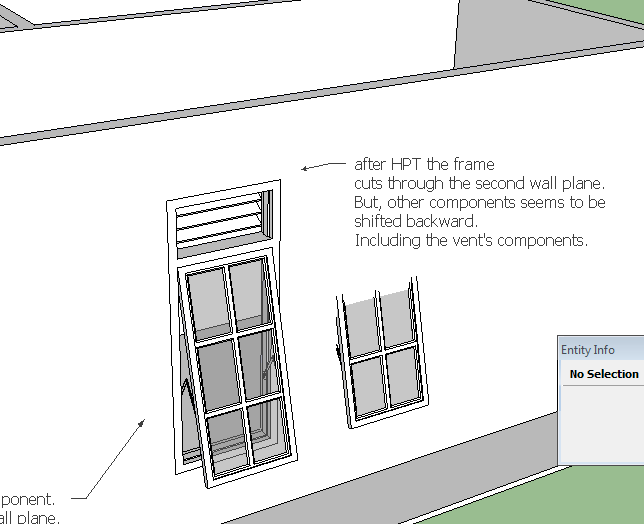
In your 'exploded' version it glues/cuts then punches correctly as you have [re]located it on the wall face.
The reason that the adjacent 'faulty' and 'unfixed' component instance jumps is I suspect because it was confused as to which face you had it glued onto and which face it might then cut. I suspect that the 'punch' simply jiggled the data-base and it decided it was glued to the inner-face. IF your components are correctly made [i.e. proper cutting-loop on the face-plane, correctly oriented axes etc] then this should not happen... -
@unknownuser said:
In your 'exploded' version it glues/cuts then punches correctly as you have [re]located it on the wall face.
actually not, sir.
the second window is the original one. hence it has the original component's name instead of "component #1". the component #1 was made after i read about the sill and misunderstood it.
really glad the tool works very well. now it's my turn to improve the way i make components.thank you, sir.
-
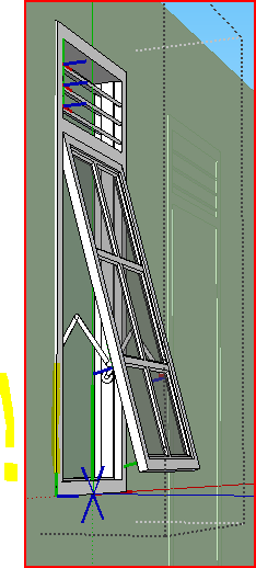
greeting, sir.
i've made another attempt to create a component that would work with Hole Punching Tool.
the tool cut the wall very well as expected.
yet, again i've made a mistake with the component create setting probably.
as shown by the image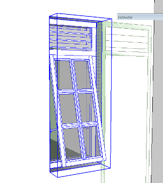
this time i've made the component with closed loop 1 cm above the window frame's plane.
and after applying HPT to the window's frame, the window shifted backward from the first wall plane.
i don't know what went wrong. i've tried to rebuild the window few more times. but still. -
Several issues overlapping...
First you have a model that is a jumble of nested components/groups.
If you place a cutting component onto a face that is not in the current active entities context, then although it glues onto it, it won't 'cut' as it has no contact with the geometry in the other context.Secondly, your 'problem' window component is made up of other components - these internal bits don't need any special 'behaviors'.
IF you want the window to cut the wall at the 'rectangle' that's just in front of the assembled frames etc, then leave it as a simple rectangle, don't weld it into a looped curve [unless you want any punched reveals to have smoothed edges], and you also don't need to make the rectangle into a component [or group], and it certainly doesn't need to be a component with any special 'behaviors' added to it - please leave it as plain geometry inside the cutting component - then it works for me when used inside a common context ! -
finally made it, thank god.
thank you very much for the tool

-
@tig said:
To make [or edit] a locale file look in the
../Plugins/TIGtools/subfolder.
There are several #HolePunchTool...lingvo files.
Copy the base file #HolePunchToolEN-US.lingvo as #HolePunchToolIT.lingvo
for ITalian.
To find your exact locale 'code' type/copy&paste this in the Ruby Console
Sketchup.get_locale.upcase
This 'code' then goes on the end of the file's name, before.lingvoin place of 'EN-US'.
Edit the new file and you'll see lines of code like this:
Exiting.<==>Exiting.
The text to the left of the<==>is the hard-coded English version and to the right the translation - obviously in the English lingvo file it's the same words!
Change the right-hand side to your locale translation, keeping punctuation and spaces etc if any, so for an IT version you might have.
Exiting.<==>Verrà chiuso.
Complete your translations and then save the file.
When you restart Sketchup the tool should display in the locale language as it'll automatically find the new file.
If you find some text that's wrongly translated, then check the lingvo file and edit it.
If you find that some text has not translated, then check the lingvo file and fix it - if the text is not actually in the file then let me know as sometimes bits of hard-coded text and the lingvo text mismatch - although I think that this one is pretty solid.TIG hello:
I translated the text for the ZH-CN, tool display in English? ? ?
-
@unknownuser said:
I translated the text for the ZH-CN, tool display in English? ? ?
Is this a question?
Or is it a statement ?
You are free to translate any tool's linvgo into Chinese [although some have been translated already].
All I ask is you zip the new lingvo file and post it in the tool's thread with an explantion, so others can use it too, and I will then package it with any future updates of the tool too...

-
Here's Guanjin's Chinese lingvo file [Thank you!].#HolePunchToolZH-CN.zipUnzip it and place the file in the TIGtools folder in the Plugins folder...
Hello! It looks like you're interested in this conversation, but you don't have an account yet.
Getting fed up of having to scroll through the same posts each visit? When you register for an account, you'll always come back to exactly where you were before, and choose to be notified of new replies (either via email, or push notification). You'll also be able to save bookmarks and upvote posts to show your appreciation to other community members.
With your input, this post could be even better 💗
Register Login


Advertisement