Drawing Steel Plates and aligning them
-
I am trying to draw steel plates and also trying to align them on various angles. I have drawn 3D objects in AutoCAD 2010 but not familiar with SketchUp.
-
While you can grab an entity anywhere with the Move tool, it makes sense to grab the entity by a logical point such as a corner. Grab the plate by a corner that will correspond to a corner on the neighboring plate. Then the tool will snap to the corner on the neighbor. Make your plates into components so they won't stick to each other and if you have identical plates, make copies of the original instead of drawing the same plate over and over.
You'll probably find it is much easier to move a plate into position and then rotate it as needed. You can set the axis for the Rotate tool by clicking (hold) and dragging along the line that is the center of rotation. After you've got two plates lined up next to each other, use the seam line as the axis of rotation.
Better than doing a lot of moving and rotating would be to draw the plates in place as much as possible.
-
Thanks for the well detail replay. I got that part down now. Now the problem I found is I wanted to oval vent holes cut out on the plate. Problem is, I draw two circles apart from each other say 6 inches, then two lines. When I got to position the circles on my reference lines closer to what I need, it stretches the plate out of proportion. I want to move the circles over to a more precise spot and then delete or push out a oval hole in the plate. I could load the example if needed.
-
You should watch all the vids by Aidan Chopra.
-
Slimdog's suggestion is a good one.
As to your oval hole, I guess what you do is dependent upon a number of things. Is the plate flat or bent? Where is the hole located?
It's probably easier to work out the correct location for the hole with a few guidelines before drawing the shape of it. Then you don't have to move it. It's sort of the same thing I referred to about drawing the plates in place rather than dragging them into place after making them. If you do need to move the hole, you should be able to select its edges and then use the Move tool without distorting the plate. Just make sure you are only selecting the hole, though.
If you want to post an example, I'm sure it'll be helpful.
d
-
Hey Slimdog, is see your also a vancouver-ite and welder. Im from Langley... I have seen quite a few of those help videos and are great. May have missed that one, will check it out thanks.
I think I will try drawing with the construction lines Dave. I have the rotation down now, similar to autocad. Just have to get used to this sticky drawing technique. Once I get them cut out, I may group them or make them components. The file size wont be all that large so it shouldn't be a issue.
I will see if I can get the example file for ya. (how do you upload files on this forum?)
-
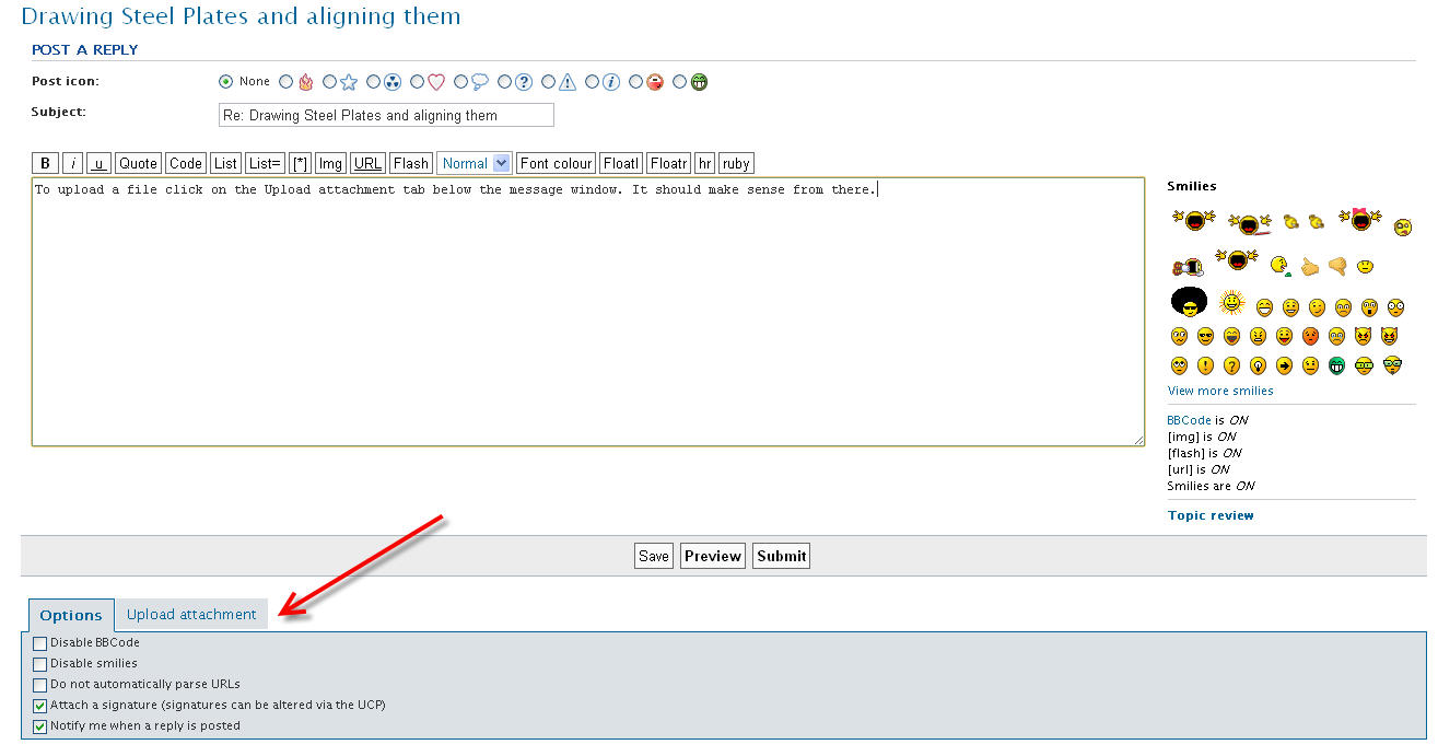
To upload a file click on the Upload attachment tab below the message window. It should make sense from there.
-
@speedy1 said:
Hey Slimdog, is see your also a vancouver-ite and welder. Im from Langley... I have seen quite a few of those help videos and are great. May have missed that one, will check it out thanks.
Are you doing shop drawings for someone or just modeling for fun?
-
I am doing shop drawings for myself. I already have what I am trying to draw finished in autocad and also sketchup. A friend of mine did the sketchup part, now I need to learn it so I can make more drawings.
Here is what we designed.

-
I think construction lines would be the way to go.
-
I'd like to see the SKP file but it looks like that model could use some help.
So if I was going to draw this thing in SketchUp as individual plates, I would definitely draw the plates in place rather than drawing them and then moving and rotating them. It would be a lot less work that way and less prone to errors. Since it is symmetrical, I would also only draw half of it.
-
@dave r said:
I'd like to see the SKP file but it looks like that model could use some help.
So if I was going to draw this thing in SketchUp as individual plates, I would definitely draw the plates in place rather than drawing them and then moving and rotating them. It would be a lot less work that way and less prone to errors. Since it is symmetrical, I would also only draw half of it.
Apparently he did only draw half of it and then mirrored it for the other half. And the plates where drawn in place and rotated from what I was told. That's the way I would do it anyways.
-
Hello
I use 1/4" steel plate in the designs I make from Sketchup. My Avatar is an example. Note, Since I am using 1/4" steel plate, I don't even use the plate thickness. I use zero plate thickness. I found it is a lot easier to make the designs and the welder just butt the inside edges together and make a weld on the outside in the gap between the plates and another weld inside between the plates. No problem.
It is a thing of beauty to see two pieces, 14' or more feet long align right up correctly at some weird angle.
Ken
-
Looks like a cool project speedy1.
If its going to be 1/4" plate it's going to weigh a lot.
What kinda truck is it going on?
Personally if I was doing it I would model each plate with thickness.
Are you guys cutting the plates by hand? -
I have built one of these and mounted it on a truck. Turned out really well. The 1/4 plate is for the front part that has the winch going through it. It also has to be able to take the brunt of a impact. The rest, top and sides are all 3/16 with a total over-all weight of 120lbs. They are build for dodge trucks.
The plate thickness is set to zero I believe. Everything worked out quite well. As Ken said, it fit together with out any thickness issues and was corner to corner. I cut the plates with zip cuts but now I am going to use a torch. (was out of oxygen on the torch at the time) Once I get some money together, I'm going to get a plasma.
Chris
-
I think the biggest issue I face now is drawing in the direction of axes. I get turned around easily and draw shapes on the wrong planes. Is there a way to take a shape and change it to say "Front" plane?
I like the small house(s) idea for view angles.
-
Ouch zip cuts. Oh well use what you've got. I once built a nice aluminum bumper for a costumer. We test fit in and he liked it. So I measured between the frame rails and centered the mounting angles on to the bumper the next day. When he showed up we mounted the bumper and the mounting holes worked out great but the bumper was out of alignment on the body by a 1/2". Stupid frame rails were offset from the body. So I had to cut the mounts off and re weld them in the right place
@speedy1 said:
I think the biggest issue I face now is drawing in the direction of axes. I get turned around easily and draw shapes on the wrong planes. Is there a way to take a shape and change it to say "Front" plane?
Select the face and right click then pick align view. That will make the face you are working on directly in front of you. I would also recommend using a separate layer for each plate.
-
So aligning with the axis is like rotating on the axis. Sweet, thanks.
Ya went through 21 zip cuts when it was all said and done haha. Had them laying around from previous jobs I have done or worked at. Now I have a new oxygen bottle, Im hoping it will be cheaper.
Hello! It looks like you're interested in this conversation, but you don't have an account yet.
Getting fed up of having to scroll through the same posts each visit? When you register for an account, you'll always come back to exactly where you were before, and choose to be notified of new replies (either via email, or push notification). You'll also be able to save bookmarks and upvote posts to show your appreciation to other community members.
With your input, this post could be even better 💗
Register Login


Advertisement