Anyone with experience in metrology
-
That is metrology (computer aided measuring)and not meteorology (weather)? I need to get a detailed set of measurements for modeling the inside of a van. Any help would be appreciated.
-
Dear Roger,
Well, you could use a laser distance meter, but deciding on a datum would be tricky. You could use a supported tube down the centre of the van, and then measure off that. You would also need a sliding protractor, or an inclimometer on your distance meter to determine the angle of the laser beam relative to the floor say. You would then to generate a point cloud to determine the overall shape.
There might be someone close who has the equipment to do 3D laser surveying. It might not be too expensive and would save you a lot of time. Hope this helps.
Regards,
Bob -
Metrology = "The science of measures and weights".
Before you can determine how one needs to determine how accurate. If you are using SU for the model then I assume the accuracy needs are not very high so using the old saying "KISS" maybe the way to go. IE grid, plum lines and tape ( or cheap laser from local big box store). Even if the VAN has cabinets etc it is almost certain you can find a location to establish an axis origin location and the old standard 3,4,5 triangle ( you can build easily) to get two perpendicular to each other. My guess is you can probably measure to plus /minus 1/4" this way. Away from the established origin you will have a plane ref , the floor (van needs to be level), which in combination with one of the axis references allows a vertical axis. If you have many high frequency surfaces to deal with then the sampling period will be so short this may not be time effective for you. For this case an interior photo match maybe a consideration ( not good for organic shapes thought)??
Just some thoughts from a non expert with some experience in missile instrumentation. -
What is inaccurate about SU" If I increased all my measurements by a factor of 10, wouldn't I also decrease inaccuracies by factor of 10? If I build a cube that I designate to be 12" x 12" x 12" will not the dimensions shown be infinitely accurate? I realise that I might not want to drive a CNC machine with the results, but it is the measurements shown that need to be accurate and not any measuremetns taken from the drawing.
I am looking for solutions that are fast and accurate. There is something called CMM (don't remember what that stands for)that uses an articulated arm that gives highly accurate readings each time you touch it to a surface. Photo matching bothers me because there is a lot of work that goes into factoring out lens distortion. Laser theodolites are interesting, but I am not sure how they will handle medium scale organic shapes with a lot of sloping reflective surfaces.
Oh and did I mention cheap?
Looks like I have a lot of research to do.
-
Do you need to make a lot of models? And accuracey to what tolerance? Can you get blueprints for the vehicle? This is a bit of an odd request, but it should be just as do-able in SU as any other modeling app.
-
You might get some good results from this system.
http://forums.sketchucation.com/viewtopic.php?f=18&t=29565&p=264538&hilit=3d+scanner#p258921 -
Box thanks for the info. This could possibly work well for me. I wish my first experience with it was not a "live fire exercise," and I have to think about how this might be applied to an interior space. The more I think about this, I might be able to do an adaption of this technique modified to meet my special set of conditions. A very interesting challenge.
-
Maybe this link to an updated boatbuilding technique might give you some ideas http://westsail42.blogspot.com/search/label/Tick%20Stick
-
Roger,
The article referenced by Nick is pretty much what I was suggesting, although better explained.
Regards,
Bob -
@roger said:
What is inaccurate about SU" If I increased all my measurements by a factor of 10, wouldn't I also decrease inaccuracies by factor of 10? If I build a cube that I designate to be 12" x 12" x 12" will not the dimensions shown be infinitely accurate? I realise that I might not want to drive a CNC machine with the results, but it is the measurements shown that need to be accurate and not any measuremetns taken from the drawing.
I am looking for solutions that are fast and accurate. There is something called CMM (don't remember what that stands for)that uses an articulated arm that gives highly accurate readings each time you touch it to a surface. Photo matching bothers me because there is a lot of work that goes into factoring out lens distortion. Laser theodolites are interesting, but I am not sure how they will handle medium scale organic shapes with a lot of sloping reflective surfaces.
Oh and did I mention cheap?
Looks like I have a lot of research to do.
CMM= Coordinate Measurement Machine( Google search) ok for planar but probably problematic for your spherical or cylindrical case unless of course you are only concerned with the walls. I would question if photogrammetry can be used for the same reason but could be worth a check. Many of the techniques can get costly quickly and I assume you have a limited budget
As I am sure you are aware there is a huge difference between measure resolution and accuracy. More is not necessarily better. SU is a mesh program and approximates curves by line segments so you will still have to answer the question of what accuracy you want and that will drive the sampling required. I cannot think you need a highly accurate system and think you must have your needs in mind before going very far with your project although taking with some of the measurement community will give you some ideas. The tick stick looks promising and somewhat along the lines I was discussing above. Cross section of a smooth hull vs your van I don't know because of zero understanding what your real requiremnts are. IE is it tricked out on the inside or???? -
this is the 'joggle stick' similiar to the tick stick mentioned before.
This is a very accurate method for taking locations of points.
the skip should explain how to use it, its real world tho, i havent looked at how you would transfer to cad, possibly with the grid printout mentioned on the boatbuilding link.
baz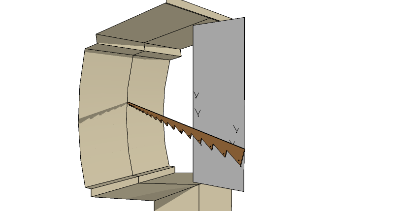
-
Barry, OK here is what I am going to do. I am going to create a large joggle board on a stand that I can move back and forth in the van. I will drill a series of numbered holes in the joggle board. I will have a laser range finder on a plate that can be bolted to any of the numbered holes. The plate will have a protractor on it. So the laser rangefinder give me the distance to a spot on the interior of the van and the protractor will give me an angle. Each time I take a reading I recorded the distance forward into the van that the joggle board is placed. Then I record the hold I am using for said measurement and the angle and laser distance to the side of the van. It is basically a polar coordinate system. The reason for multiple holes is that some interior overhang or fixture might block the laser and to get around that the board needs to have multiple reference points so the laser is never blocked. Then in SU I just set up as many joggle boards as I need and from the reference holes I draw lines at the appropriate angle and distance. I then connect the dots on each board.
Lastly I skin the outside edges of the boards just as if I were making an inverted boat hull. Tedious but workable.
By the way I have seen an improvement on the joggle stick. Don't make it like a regular saw tooth. Instead use a sabersaw to cut a French curve like inner portion of the joggle stick. Then the paper that covers your board will not be covered with identical V's which will be confusing or need a lot of numerical notation. When you go back to loft your lines you just fit the unique curves of your stick to the lines from the paper and the points of your outline will be accurately reproduced. And if some of the lines get too close to each other, use various colored markers to make your joggle board tracings stand out.
So I want to thank all who contributed and helped with my thinking.
Plan A is a LAJB (Laser Aided Joggle Board)
Plan B is a Mysterious Cash Infusion (MCI)from an angel (or angle)investor.If this project is a go, I will post photos of the whole process.
-
roger, sounds workable, if, as you said, a bit tedious. you will have to ensure that your joggle board can be kept exactly planar and vertical with its previous position/s but with a flat floor should'nt be too difficult
.
i have no experience with measuring lasers, are they accurate enough in the range you will need? (1000 to 2000mm i expect)please do inform us of progress, i might try it myself when a suitable project comes up. til now i have only needed the joggle stick to fit cabinetry, bulkheads etc to boat hulls, but with laser/plasma cutting becoming viable economically it could be good to have accurate su drawings.
baz -
The low-end Bosch Laser distance meter claims an accuracy of +/- 1/16 inch over a distance of about 130 feet. I don't know if it more accurate over shorter distances or if that is the cumulative error for 130 ft.
-
The problem with all laser measurement equipment is it's super accurate [compared to a tapemeasure or traditional level] BUT you have to make sure you know exactly what is being measured by it [from/to] - e.g. if a panel is even slightly 'profiled' or 'curved' then are you measuring from/to the near-side or far-side of the profile, or if there are projecting fixings are you sure you didn't measure to one of these and thereby remove several mm from the dimension etc etc - I recall 'in the old days' taking levels with a staff and quick-set level, my junior assistants would be forever working things out to ~1mm - since you can't measure in the real world to that accuracy, e.g. you might have put the staff on a 10mm pebble or when the guys come to use you info on site later a tractor has probably run over the same ground and changed the level by cms !! I was happy to go to the nearest 1cm...
You are measuring up so you can design 'fittings' - presumably these will either include some built-in tolerances and 'back-spaces' with detailing to accommodate the 'join', or they'll be made "bespoke" and will be individually measured to fit the spaces in situ - in either case the final accuracy is not completely dependent on your detailed designs as there'll either be some 'slack' or the guy fitting it will simply make his adjustments anyway ? These spaces you are measuring... you will measure one and you can't be sure that the equivalent space in its "siblings" will all be the same dimensions anyway... as they will have been built to some tolerances too... Imagine you were actually measuring this to build it without the blueprints... what do you need to measure/record ?? If you work 'backwards' you are likely to make a 'boxy' object to build-in - you have an approximate idea of what this might be, choose an SOP [setting-out-point] and 'construct' a virtual version of this 'boxy-form' within the space and measure from its key vertices to points on the existing surfaces... Just ideas, as someone else often says........

-
Hello Roger,
Please explore these links :
http://synthexport.codeplex.com
http://www.pixdim.com
http://therion.speleo.sk
http://paperless.bheeb.ch
http://www.3hconsulting.com
http://www.theposthole.org/read/article/5These are some solutions for 3d surveying.
Greetings,
Bep van Malde
-
Possibly already commented on in some of the above links- I didn't check- would be to look at Leica line of Disto Laser Distance Meters. Not inexpensive, but highly accurate.
Hello! It looks like you're interested in this conversation, but you don't have an account yet.
Getting fed up of having to scroll through the same posts each visit? When you register for an account, you'll always come back to exactly where you were before, and choose to be notified of new replies (either via email, or push notification). You'll also be able to save bookmarks and upvote posts to show your appreciation to other community members.
With your input, this post could be even better 💗
Register Login


Advertisement