Need help with several questions: windows on curved surfaces
-
Attached is a model I have been working on and having problems making window components as most of the walls are curved.
Usually, when making a window component I make it right after selecting the face, This works but for some reason on curved surfaces I am having an issue.
I have also tried to explode the component and whilst still highlighted, make it a component again with glue to any or vertical. However, when I move it down, it does not cut into the face. Also, if I take it out of the component browser it does not orient itself in the way I expect it too.
Can some one kindly take the time to look at the model and set me straight..... Thanks :O)
Also I have been trying to use Chris Fulmer's wonderful Bender plug-in to make the right hand side window and door component bend to the shape of the wall. I know how to use the plug-in, ( or at least i think i do ) but perhaps due the line work I made the model with, I can't get it to bend into the shape of the curved wall.
Should I be ensuring the curved wall line is exactly the same length as the component? I have been doing that, but not sure how to get the line set up. Do I divide it into segments or draw additional lines perpedicular to the edge and then remove them< or what? Please refer to the model where it is shown.
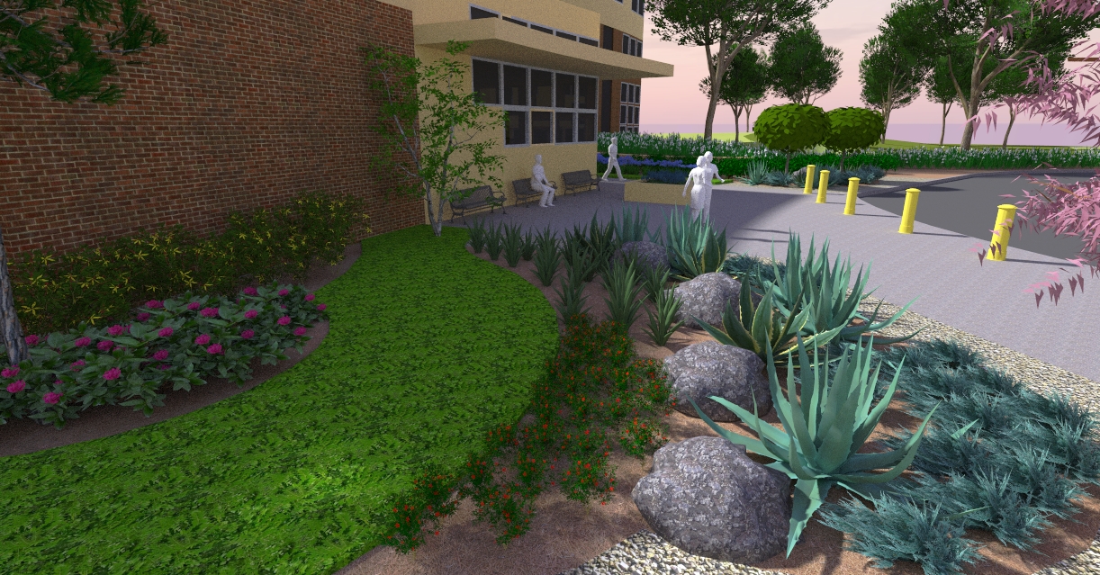
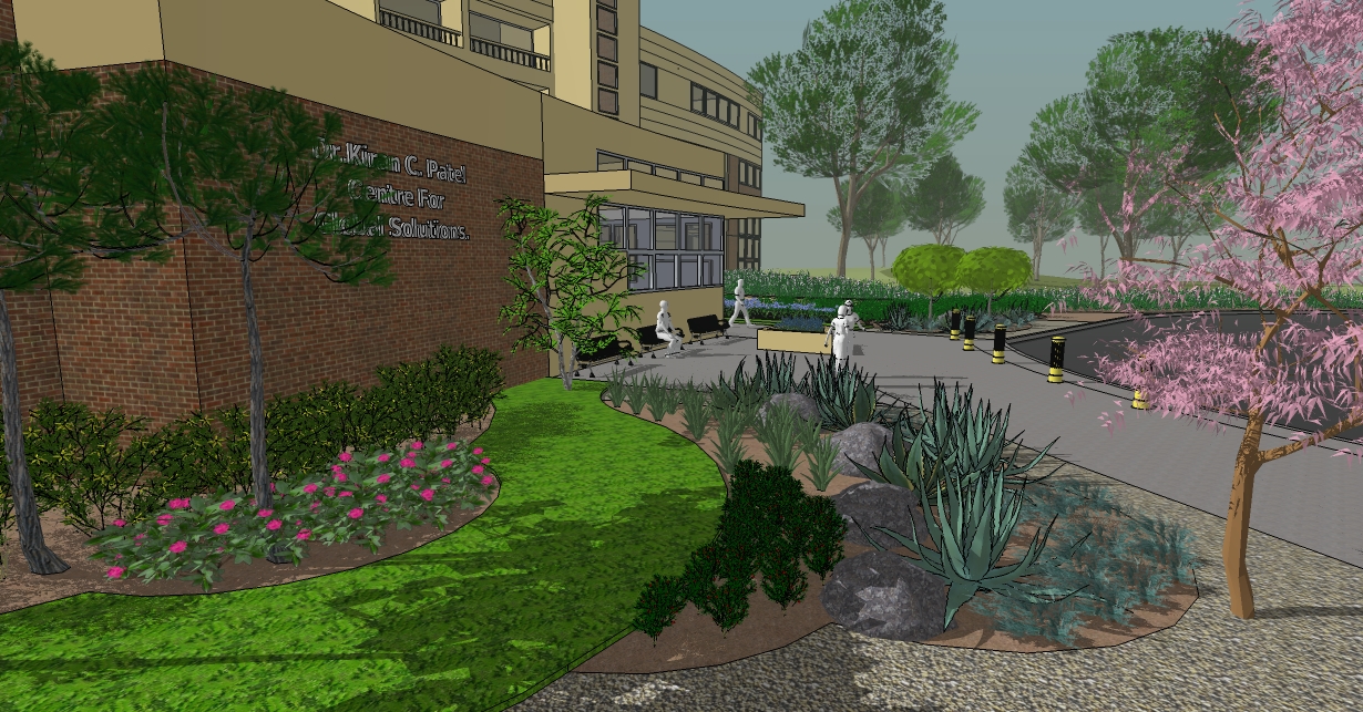
Lastly, can someone tell me why the tree in the native SU render has a very see through appearance whilst the twilight render has a full looking tree. How do I get the large sized grouping of green trees -in the background -to appear full when using SU renders?

 USF 521 Bldg.skp
Sorry for the pic size Tinypic wouldn't let me upload these for some reason...something I'm doing wrong. Just like in my model :O)
Thanks again for any answers.
-
Ref the windows on the left side: The multiple pane windows cannot be set to cut opening because of the arc radius of 213.6175 ft. The cut is referenced to how you have the component axis set and this a single planeref and therefore the problem. For that area the arc segment length is 6.72184 ft and the components now are set to bend slightly at those points. Suggest you try and modify the three pane windows to a single pane at the center line now showing since that is the 6.71284 ft. and then you can set the cutting plane and just install as many as you what ( 2,3,4,5 panes etc) along those segment lengths
Using shape bender should work but given that would be done over say three segments the bumpy look would not look good unless you want to and more segments??
Will look at the other areas as time permits. -
arclandesign
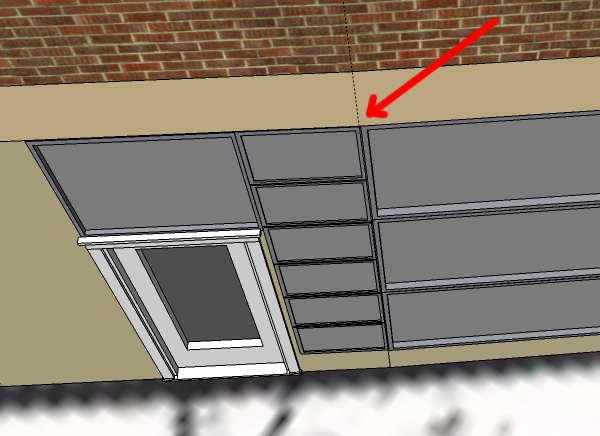
Quick look at your "other" window problem. Shape bender will work but, there are some problems with your component model. There are some dimension problems, one side vs other different lengths, some below plane points vs others points at zero, some lines are not on axis. I think this is causing some intersect problems. You need to correct these or you may have some down stream problems
-
Mac1, thank you sooo much for taking some time to look at this. It is much appreciated.
Your comment on the "single plane ref" didn't make sense to me when I read it last night, but now, having mulled it over, it has finally sunk in, and makes perfect sense. Thanks, again, for clearing that up for me

I only had a scan of the building footprint to go on and tracing over those curves was done without any foresight, or clear understanding of what I'd have to do later with the windows.
I have started a new model taking into consideration the segments I will need in each arc to make the windows fit properly... Its kinda hit or miss and a guesstimate at best, as I only have a few pictures of the building to go on, but think that now, I'll be able to accomplish this much better.
The "door/ window combo" component was originally made with tools on surface as well as with joint push pull and I'm kind of new to using both. This time round, I'll draft as much as possible on a flat surface and then try drape it as well use Shape bender as an alternative to make those window/door components work.
I'll keep on keeping on ... Thanks... One more time :O)
-
arklandesign Updated mac3 file. Did not set axis and import of widow lites were off plane some what
Here are updates to the door lites combination. I took the one in your model and redrew to try and get every thing in plane. The original issue I had may have been an artifact from the original bend or not I could not tell.xxxxxmac2 uses shape bender. If you decide to use that Program you will need to increase the number of segments in the ref curve because two in the model is not enough to get a good fit. If you look closely there are still a few artifacts I don't understand just yet. Also there is a bug flagged by Chris Fullmer in the SCF plugin forum wherein the last segment angle is not "correct" although I don't think that is causing the issues I see.
xxxxmac3 uses components. I made the door and two top lites as one and another from one of the side lites. You can install the door then since it will fit within the arc segments you have drawn and the I just scaled the lites in that same segment to fit to fill it.(I would probably redo this to use the golden rectangle criteria to make it look a little better) The adjacent ones will fit w/o scaling. Noteif you don't want the side stiles to be different widths because of this scaling you can use Fredo's scale tool in the stretch mode to prevent that problem. That is one of the issues I have with the shape bender maybe and still have to check.USF 521 Bldg_mac2.skp
Not sure you need to redo your total model. Think you can make do with what you have
-
Mac1 Thanks again for your efforts, apologies for delay in reply but middle daughter had an appendectomy a few days and now doing fine :O)
I will look closely at the both models to learn a bit more.However i did redo the entire model. It only takes ten minutes to create the mass of the building
I have attached a new model with refinements to get it closer to actual building (designed By Ponikvar & Associates)Funny how one can think one knows stuff in sketchup, only to find there's plenty still to learn and bad habits to remove.
One problem i need clarification on is setting the axes. Usually this is aligned to the left hand side
but as shown it is appearing on the right hand side. I have moved it to the left, but am wondering why it is aligning to the right hand side.
Also I made new window door components but am having a tough time getting them to fit onto the walls
USF Base Bldg New v2.skp
I'll keep on keeping on, but all advice is much appreciated.
Thanks again :O)
Rashad -
The last component you just make is not on a single plane. those component you just created is at a curved surface. if You unhide the hidden geometry you will see your problem (to unhide hidden geometry go View -> Hidden Geometry) .

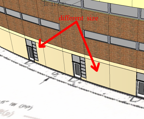
My suggestion is create the component that on a single plane. Remove the two windows that isn't on the plane with the door. Then place them on their place. But There is a different size of area after you place the door, so you cant just put the windows next to them.

-
Too funny... I must have been having a brain fart of a day... I feel

Thanks for clearing that up...all is good now :O)
Advertisement


