Construction & Working Drawings - Discussion
-
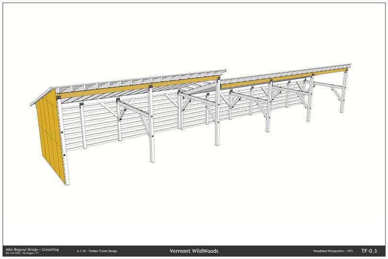
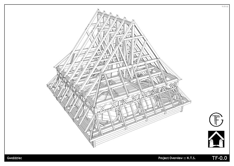
A new project... getting a bit faster. Still wishing for some more intuitive tools, and still wishing LayOut wasn't so damned slow...
-
bmike,
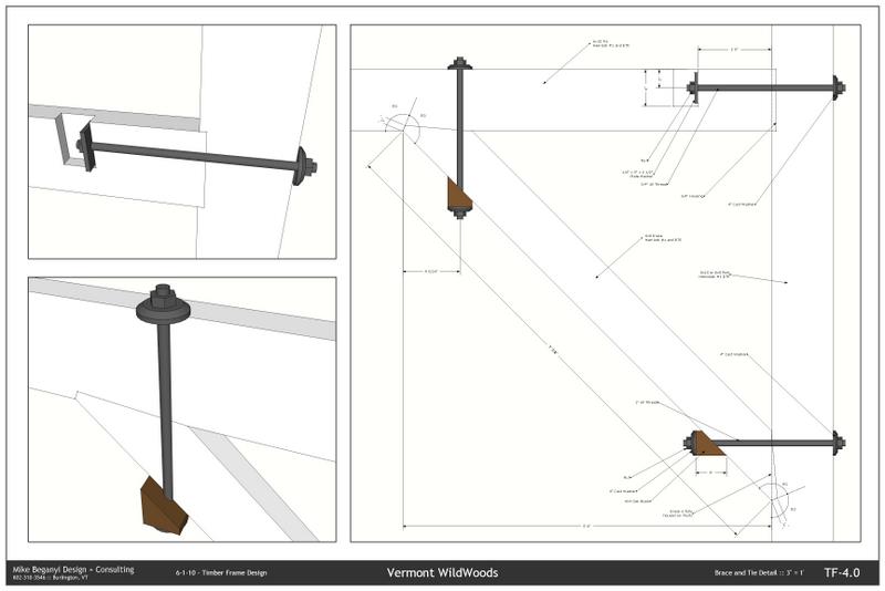
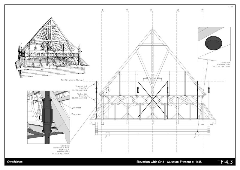
I am really liking these drawings. The 3D bolted connection details are great

-
@unknownuser said:
bmike,
I am really liking these drawings. The 3D bolted connection details are great
thanks...!
-
@dale said:
Another example of this is Atelier Bow Wow.
hoooooly cinnamon buns!!!! this looks awesome, i'm already trying to forget about autocad and this is how i want my drawings to look like
-
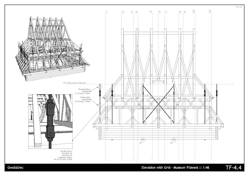
Wow that's nice, I like that the bolts are textured and colored so the details are idiot proof. These days you need to make everything as clear as possible because assuming people know what they are doing can be a big and costly mistake. A person experienced in layout can really make a job go much more smoothly and save money too. Those drawings with the bolt details is a perfect example. Thanks for posting it.
-
Hello for all. I,m architect using SU 6 with LO. I'm using SU for the last 11 months, first to develop 3D model to customers. All CD was done in CAD. By now, after seeing LO gallery and earlier posts I decided to include LO to CD. I did prepare many scenes with floor plan, elevations and sections, but when I put scenes in the LO viewports the sections planes are still highlighted. Anyone could help how to fix it?
Thanks in advance.
Riceles Costa
-
Hello. After posting my question I returned to the SU and fix the problem. It is enough use "hide" in each section plane, save the file and update LO file. Very easy.
When my drawings are finished I will post here.
Riceles
-
Hello to all in this thread
I have just uploaded to Google Warehouse my set of Electrical symbols and structural symbols including the Elusive DASHED LINE! To use the electrical symbols just open each component and hide the version you do not want. For the dashed line and arc just scale them to the drawing, edit component and get rid of the very stretched circle. For those who want to fine tune the process of creating dashed lines and get them to the right look for their projects here is the info: painful as it is, for a straight line you must draw a set of equal lines with equal spaces between (or any regular variation, I think mine were 1/4" each) and - here is the key - add a small circle to one end. Then make a component of it and it is scalable.
 For the arc I just drew an arc, exploded it, made a component of it, and hid every other segment in edit mode. It too is scalable.
After digesting every word in this forum topic it is time to give back to you all. At least I hope this is an original idea or I will feel real stupid
 the URL: http://sketchup.google.com/3dwarehouse/cldetails?mid=ead79f519f67b4c28fb37abf337da9ec&ct=mdcc&prevstart=0
Thank you all for the great info.
Klog -
Hi Klog,
Thanks for those! I am not in this trade but I understand it will be extremely useful for some people!
-
I am very much impressed with the capabilities of SU... but I find CAD applications more easy and the results are more perfect the 3D view is also more accurate without containing any mistakes and it is trustworthy. I have been using CAD applications for about more than 2 years and I'm loving it
 but there can be some more things that can be done by integrating both CAD applications and SU, like the use of DataCAD 12, import the SU features and then have DataCAD generate 2D elevation drawings. It can take a few minutes, but still quicker than recreating them from scratch, and cleaner than importing a dwg file from SU. So it can be more useful that just using a single software
 -
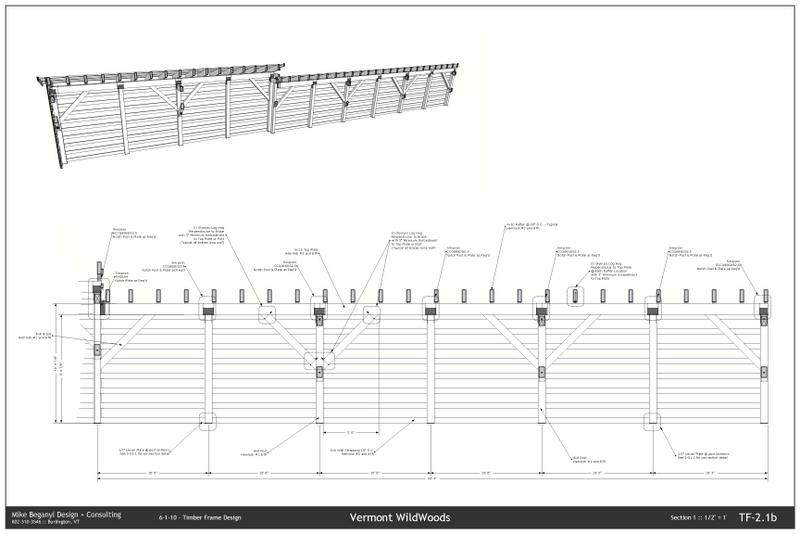
Another recent project:


-
@rockersujith said:
I am very much impressed with the capabilities of SU... but I find CAD applications more easy and the results are more perfect the 3D view is also more accurate without containing any mistakes and it is trustworthy. I have been using CAD applications for about more than 2 years and I'm loving it
but there can be some more things that can be done by integrating both CAD applications and SU, like the use of DataCAD 12, import the SU features and then have DataCAD generate 2D elevation drawings. It can take a few minutes, but still quicker than recreating them from scratch, and cleaner than importing a dwg file from SU. So it can be more useful that just using a single softwareI completly disagree. Accuracy is not a problem in SU, architecture wise.
The simpliest and fastest way to do elevation (or any drawing) is SU+Layout.
So, in a way, you are right in saying not to use just a single soft. -
@rockersujith said:
... but I find CAD applications more easy and the results are more perfect the 3D view is also more accurate without containing any mistakes and it is trustworthy.
I don't agree with your assertion that SketchUp is inaccurate or creates mistakes. SketchUp is definitely capable of very high accuracy and precision. Mistakes or lack of accuracy are induced by the user.
-
@dave r said:
@rockersujith said:
... but I find CAD applications more easy and the results are more perfect the 3D view is also more accurate without containing any mistakes and it is trustworthy.
I don't agree with your assertion that SketchUp is inaccurate or creates mistakes. SketchUp is definitely capable of very high accuracy and precision. Mistakes or lack of accuracy are induced by the user.
agreed. sketchup is as accurate as the user makes it.
-
Hello,
I'm trying out the combination of SU and LO as an alternative to CAD. I added a picture from a test.
The picture at the top is a perspective view from SU, rendered in LO as vector. I added the dimensions in SU because there I'm sure which points I'm measuring. In LO the dimensions are sometimes off.
Question: can the leaders of the dimensions in SU somehow be hidden? I prefer just the slash.The second picture is a section cutface with the hatches from SU, rendered in LO as raster.
Question: Is there a way to improve the quality / crispness of the hatches? I use high res images as textures and my output quality is set to high.The third image is the section cutface without textures rendered in LO as vector.
The last image is a combination of all of the above in LO.
I'm not unhappy with the final image in LO but I would like to improve some elements. I hope someone has an answer to the questions.
Greetings,
Max
edit: added the pdf
-
Kaas
"Question: can the leaders of the dimensions in SU somehow be hidden? I prefer just the slash.The second picture is a section cutface with the hatches from SU, rendered in LO as raster.
Question: Is there a way to improve the quality / crispness of the hatches? I use high res images as textures and my output quality is set to high."
As far as I know the leaders for dimension lines cannot be altered - LO or SKUP. Second, I created some clear hatches from AutoCad by hatching a box in AC and making a jpg of it. Choose the lineweight in AC. Save the jpg where you would put .skm files, crop for tiling, and create a new material in SKUP using that jpg.
The "hatches" (read materials) in SKUP are subject to inherent styles apparently (someone correct me if wrong)and often include some screening effects.
I prefer the dimensioning to be done in SKUP for the same reasons you do. I will attempt to attach the concrete hatch made in this fashion.
Hope this helps some.
Klog
-
Hello Klog,
@unknownuser said:
As far as I know the leaders for dimension lines cannot be altered - LO or SKUP.
In LO they can be altered. Just double click on a dimension and you get some extra grips to alter the leaders.
@unknownuser said:
Second, I created some clear hatches from AutoCad by hatching a box in AC and making a jpg of it....The "hatches" (read materials) in SKUP are subject to inherent styles apparently (someone correct me if wrong)and often include some screening effects.
It's a nice material you created but I think the base resolution of the texture in SU isn't the problem (I use 256x128 or 512x256 for a simple hatch like the attachment). I still would like to improve the sharpness in LO for those SU-hatches.
Greetings, Max

-
Max
If you are using the stock hatches that come with Skup then you probably cannot change the sharpness. When you make your own you bypass that problem unless the style you are using for the scene incorporates some fade-out (fog). Thanks for the info on dimension leaders ...
Al (Klog) -
-


Hello! It looks like you're interested in this conversation, but you don't have an account yet.
Getting fed up of having to scroll through the same posts each visit? When you register for an account, you'll always come back to exactly where you were before, and choose to be notified of new replies (either via email, or push notification). You'll also be able to save bookmarks and upvote posts to show your appreciation to other community members.
With your input, this post could be even better 💗
Register Login


Advertisement