Scaling of distorted ground floor layout
-
Hi everybody. I'm working with a group of fellow newbie SketchUp planners who intend to model the houses of our village. We rely on architecture plans showing the layout of the ground floor as well as images of the facades. The design process starts by importing the scanned plan of the ground floor. The plan is scaled to approximately the real size. Then we place guides along the outer walls and insert dimension shapes to indicate the main measurements. This is good for the design process and we intend to use a 2D rendering of this layout to prove that the design has correct size when the model is submitted for publication in Google Earth. - At this point we group all these entities, to keep them connected while scaling.
It is very easy to scale the image to exactly correct dimension in one direction. Every newbie should know that this is done by using the tape measure tool. The distance between the two outer walls is being measured by toggling the tool with the Ctrl key into the measurement mode (no plus sign). Then the measurement visible in the architecture plan is entered. By pushing Enter and accepting the resize, the image will scale in both directions to accommodate with this value.
This should do the job. We actually do get the exactly correct dimension... in one direction. Unfortunately the architecture plans are never very precise and the scanning process may enter distortions as well. But we would like to have both main dimensions exactly correct (which will also please the GE evaluators).
It is possible to gradually iterate towards the correct measurement in the second direction by using the scale tool, but this is a bit cumbersome and tedious method. - Does anybody have a speedier procedure to arrive at the exactly correct second dimension?
-
The tapemeasure tool is a quick way to 'scale' the whole thing in every axis...
Use Scale for one axis, and type in the required dimension for that axis [size], with a units suffix - e.g. 20'6" or 6m - it will scale in that axis to that size - no 'tweaking this and that' is necessary...
You can also scale in the other axis by any required dimension too...
Type a number scales by that factor BUT giving a dimension suffix makes the scale in that axis that dimension.

-
Thanks TIG for your kind advice.
@tig said:
The tapemeasure tool is a quick way to 'scale' the whole thing in every axis...
I think that the tape measure is even more handy than that. You can actually scale any part of the image to an exact size by typing in the required dimension. The problem is that this doesn't give access to the other dimension.
@tig said:
Use Scale for one axis, and type in the required dimension for that axis [size], with a units suffix - e.g. 20'6" or 6m - it will scale in that axis to that size - no 'tweaking this and that' is necessary... / You can also scale in the other axis by any required dimension too...
Quite correct. The need for tweaking arises from the fact that the other dimension is in the image. This puts us in a situation where we don't actually know the other outer dimension (before it has been scaled).
I'll add an image to make the scenario I described a bit clearer:

But is there a handier way of fixing the other dimension?
-
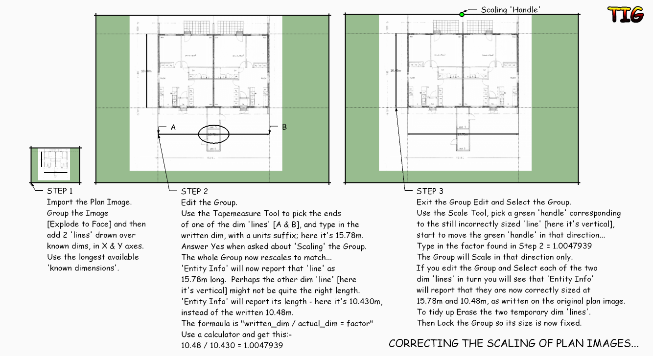
They way you are doing it is pretty much the right one, BUT here is a one page tutorial on what I think is the easiest/best way...
-
Thanks TIG. You produced a very nice enhancement of our scheme by offering the TIG two dimension scaling formula that was really missing from our scheme:
layout_dimension / model_dimension = scaling_factor
To be honest: There are still a couple of fine details that we pay attention to in order to get it all right. We play with the snapping and resolution settings of the Model Info > Units property sheet while setting the guides and moving back to scaling.
And yes, it is indeed a good idea to lock the group after successful scaling.
TIG's tutorial sheet is excellent. I summarized our findings in Finnish on the web site of the group: http://sites.google.com/site/iivantiira3d/rakennuspiirustuksen-mittakaavan-asettaminen.
Hello! It looks like you're interested in this conversation, but you don't have an account yet.
Getting fed up of having to scroll through the same posts each visit? When you register for an account, you'll always come back to exactly where you were before, and choose to be notified of new replies (either via email, or push notification). You'll also be able to save bookmarks and upvote posts to show your appreciation to other community members.
With your input, this post could be even better 💗
Register Login


Advertisement