Type faces for drawing street maps
-
I have been using SU (free version) for about 6 weeks. My first major project is to draw a street map to scale. I decided to use SU because eventually I can "drape" my map over 3D terrain created by drawing contour lines. I chose to label the streets with 3D Text because I want to place the letters carefully and permanently in relation to the street outlines and the other letters used on the map. Part of this intent is to have the letters scale exactly with the street outlines when the map is printed out at various enlargements. This is desirable over a certain range of scales, as opposed to having the letters scale separately, or not change at all. From my reading of various books and sources, I gather that 2D Text is meant to either stay "on the screen" or to re-position itself according to the view of the model, and either face the viewer or one of the principal axes. So I chose 3D Text.
My current problem appeared when I first attempted to print out my map on my new Epson Workforce 1100 ink-jet printer. It can print beautiful sharp renditions of the street outlines at certain scales, but the strokes of the letters fatten up and render them illegible. Alternatively, it can print beautifully legible letters at certain scales, but some (not all) of the street outlines are faint or even disappear completely. So far I have found no scale at which both features on the map print correctly.
I know that the conversion of vector-based models to raster-based printer files involves a lot of computation and sometimes some unfortunate compromises because of the fixed dimensions of the pixel grid. But I don't know how to get at the controls that would allow me to fix the problems, for instance by choosing the right
font, size, scale, pixel resolution, or other parameters.Please direct me to any source where I can read about these problems, if it's too hard to explain.
For example, are there any "Type Face Sample Sheets" in which I can see how they print at various sizes?
One hint that may shed some more light on my problem is that the same "edges" (lines) have the same printing problems consistently. That is, if I direct the Print routine to create a PDF instead of directing it to the printer, I can see that the edges which disappear have extra gray pixels, like an anti-aliasing technique. The lines that print clearly show only sharp, black pixels. I suspect that this may result from some setting in the series of
panels in which I choose the parameters for rendering the model for printing.Thanks in advance!
-
Do you have any example images of the problems? That might help sort this one out.
Also, what "style" are you using? The defaul straight edge, or are you using a sketchy edge? I would think that this could be cleared up with straight edges.
And on top of all of this, I prefer to aslway export to a .jpg or .png image first and then print from there. I find that I have more control over lineweights that way. But I tend to prefer to export at a very high resolution, then downsize the image and then print. That reduces the edges greatly so that they do not stand out at all, which is my preference.
Chris
-
I wish I could provide an example. I have been trying for several hours to draw one.
For some reason I cannot fathom, the Font choice controls are grayed out, so although
I can select a font, I cannot push the radio buttons to switch between point size and
"height" in the units used in the model.At some point, many drawings ago, I chose to make the letters 50 feet high, which
sounds insane but makes perfect sense if you are mapping a city region about 5000
feet on a side. Now, SU insists on making letters 50 feet high on a model 8x10 inches,
which is not very useful.The books by Aidan Chopra and Chris Grover offer no clue as to where to find
the controls for 3D Text. Just like other documentation, they assume that it works.
By contrast, I find that if I choose Arial Narrow Regular, it ALWAYS gives me italic, which
I can correct only by choosing Italic (!) and THEN picking Regular again. As for the size,
there is no way to change the 50 foot box -- it's grayed out too.I find much to admire about SketchUp, but as a tech writer of 21 years experience,
I find it hard to believe that this software is ready for release. Please help me
understand how it is supposed to work. I know it has been used and developed for
ten years already.I began by drawing a box 8 inches by 10 inches, and then added a grid of lines
accurately laid out in units of printer's points (1/72 inch) to compare to the type face
reproduction. But so far I have been unable to place a single character of 3D Text
type into the box.If someone else can make such a drawing, it might help me and other people to
understand how 3D Text is supposed to be used and printed.Thanks in advance for any advice.
-
Sorry, Chris, I forgot to answer your question about styles.
No, of course I did not apply a "sketchy" style or any other
style modification. This is a map, and it is trying to be as
clear and sharp as any street map from professional cartography.-- Ray
-
Hi Ray,
As far as setting the size of your 3D text, please see the attached image below. In the box I have circled, just type in the height you want your text to be. Italics are set in the box right above height adjustments. I cant help on your printing problems tho...someone else may chime in about that

-
Hi Ray,
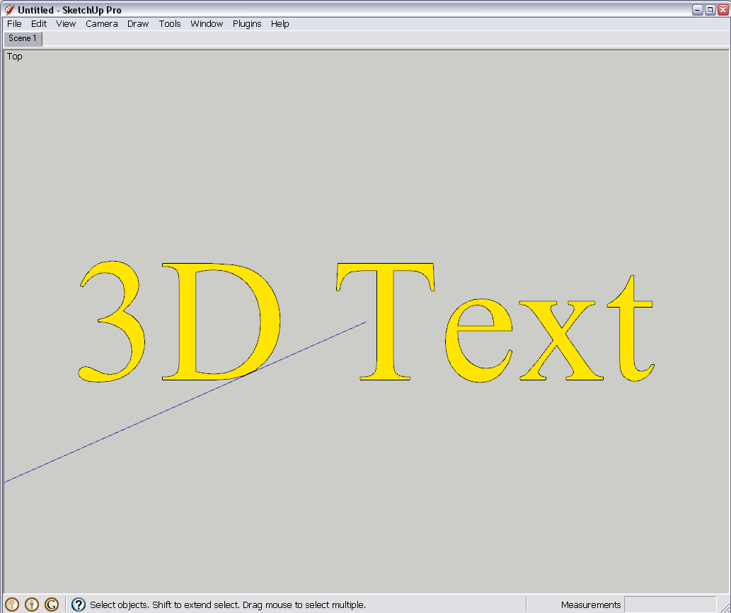
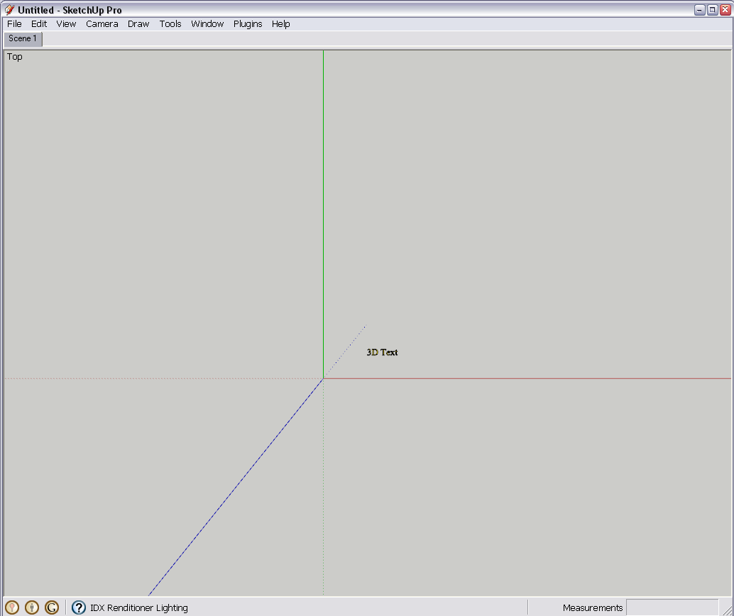
I see your problem. Say this is a 3D Text from close-up - all seems to be fine.

Now if you zoom out, the edges in SU will always display as 1 pixel on screen (and print) regardless of the face already foreshortened and eventually disappearing and the letters displaying as a black blob.
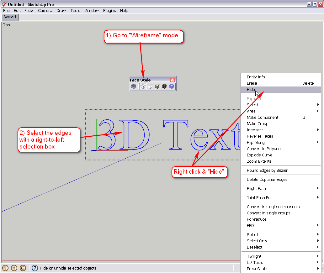
The solution is to hide the edges of the 3D Text. Enter the group, go to Wireframe mode (if you do not have the Face styles toolbar activated from View > Toolbars, use the View > Face styles menu item), select the edges and hide them. After closing the group, these "always 1 pixel" edges won't disturb you any longer.
-
My '2D Tools' contains a '2D Text' tool that makes 'flat' 3D Text to your desired text/font/color/size etc with or without edges etc [remember to include \n in the text for any line-breaks] - it snaps to any face and is slightly offset to avoid z-fighting. It also allows you to select any piece of 2D Text later on and through the right-click context-menu to Edit it - changing its 'text' or any other properties - which is something you can't do with plain 3D Text out of the box...

-

Yes, Ray, it is obvious that since you use so many pieces of 3D Text, TIG's plugin would be very useful for you (even though you know the "trick" above) to speed things up.
-
Thank you for the replies to my problem.
Please note that I use MacOS -- does Tig's plugin work with that? (Tig uses Windows, according to the profile. If it would work, I would like to be directed to how to obtain it. It certainly seems like a sensible improvement -- why wouldn't SU work that well without Tig's help?
As for the "trick" method of hiding the edges, I haven't tried it yet, but I wonder. Since SU refused to make the 3DText "Filled" no matter how I tried to specify that, I had to "fill" each piece of text manually using the Paint Bucket tool loaded with black "paint" to fill in the edges. In the future, would I have to keep doing this and then hide the edge that was needed to accomplish a "fill" operation?
And having hidden (not deleted?) the edge, would the "fill" still serve as legible 3DText ?
As for d12dozr's suggestion, please remember that my font controls do not look like that (Windows versus Mac again) and what's worse, they are apparently permanently grayed out so they do not work.
I cannot change to point sizes, or alter the 50-foot height.I still don't see where the italic default and the 50-foot dimension are coming from.
Would anyone care to address that question?
I may not be able to participate in the discussion for a while -- I am having other problems with some aspect of my internet connection that no one has been able to fix yet.
Thanks for your attention to my problems.
Ray -
Ray, when you say you "had to "fill" each piece of text manually using the Paint Bucket tool loaded with black "paint" to fill in the edges..." it means that there were already faces - just not coloured faces.
Note that you can colour them two ways - one is to enter the group (double click to edit) and paint each face individually, the other is to paint the whole group "from outside" - in this case, it is just one click.Yes, TIG's plugin should work on the Mac with no problem. Download it from the very bottom of his first post here:
http://forums.sketchucation.com/viewtopic.php?f=323&t=22091As for your 3D text dialog and the Mac interface - I cannot comment on that either as I am also on a PC however I believe there shouldn't be any serious difference and especially in the end result of placing those text elements. This is how the Help Center explains 3D Text and its dialog etc.
http://sketchup.google.com/support/bin/answer.py?answer=94975 -
It certainly does look like TIG's tools will help.
I downloaded them from the link, and put the folder
in the subdirectory under the Mac OSX Library path
as directed.The instructions say that:
"The 2D Tools can be accessed from the "Draw/2D Tools" submenu..."
(but they don't appear there yet)
"... or, perhaps more readily by the "2D Tools" toolbar, which can be
opened from the "View/Toolbars" submenu."(but they aren't there yet either, and the name is slightly different)
So I must need to do another step or something.
In my Mac OSX version 7.1.6859 of SketchUp (free) there is a submenu
View > Tool Palettes
which shows just three options, namely:Large Tool Set
Google
Dynamic ComponentsSo, perhaps my installation isn't done yet? -- Ray
-
Ray,
As a Mac User, I can vouch for TIG's 2D tools working in OS X. You need to check the menu item as shown below to see a toolbar-

If you don't see this option, check that your Plugins folder is properly located at root level, not User level - in fact there should be no Plugins folder at User level although some things create one there.
The tools should still appear in the main "Draw" menu without a specific toolbar showing.
-
Thanks Chris -- my plugins folder is not in the User hierarchy.
I think I followed instructions from some ReadMe file in placing it,
but for whatever reason, here is the current complete path:Macintosh HD/Applications/Library/Application Support/Google SketchUp 7/SketchUp/plugins/2Dtools_4
The application installed itself from the download with the following path:
Macintosh HD/Applications/Google SketchUp7/SketchUp.app
If this doesn't look correct, please copy and correct the path(s) as they should look.
Remember, even though I need plugins, I am a Newbie
 hence this Forum.
 -
I am attempting to upload a file of the map I have drawn,
with almost all its content deleted in order to reduce its size,
which has been called "titanic" by at least one SU user.a tiny sample of the map I have drawn
Hmm -- that looks more like text than anything else.
That was the result of the "Place inline" option shown below as I entered this post.
Well, you can see the file name.
-
Well, I'll be dipped in India Ink, as we say in this country.
It does seem to have made a 1.82 MB file available for you to play with.
Now Gaieus can do the operations I was not successful with.
I tried to select and hide the edges of the type elements, leaving
the "fill" of black "paint" but did not see the expected results.In any case, you can see the problem, because of the geographer's scale of
the map I am drawing. You can see a scale in feet above the map excerpt.The complete map fills the bounding rectangle and the file is approximately
30 MB, which I had no way of perceiving as abnormally large (I'm a Newbie,
remember) although I had to be patient as it loaded, etc.My hardware is pathetically modest (a little MacBook laptop) so I may well
have bumped against some practical limits and need to move up.The fundamental problem is that I hope to print this image at a scale
of 1 foot to 5016 feet in order to create a handy map. It appears (this
may not be true) that the Line Weight controls in the free version of 7.1
apply both to the edges ("line segments" in ordinary parlance) and the
edges (in the usual sense) of the characters of type rendered as vector graphics.This means that when type is small enough to fit into small crannies on the map,
the street outlines are too narrow to print at 300 dpi -- and if they are thickened,
the type fattens up and becomes illegible.I haven't had a chance to work with 7.1 Pro to see if Layout can deal with this.
In addition, the Export restrictions on the free version have kept me from
trying to use other applications (such as Inkscape) to work on an exported
vector file.I hope that TIG's plugins will let me keep the file in SketchUp, which has done
a good job with the project up to the final point of printing it out for the ultimate use. -
Ray,
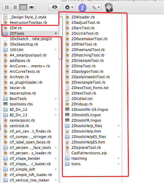
This is what you should see in your plugins folder (CadFathers Icons.zip is optional - another set of icons.)
Advertisement


