Question about cylinders
-
Hi everyone,
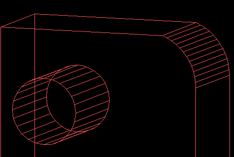
I'm new to the sketchup and I've only done some simple drawings with auto cad before. I have question regardgin to the cylinders. If I export cylinder as .dwg and open it in auto cad, the are two lines in both ends. Here is picture:
http://www.aijaa.com/img/b/00608/4753142.jpg
Why are there two lines? When I draw cylinder in Auto CAD, it only has one line in both ends and four "side" lines. I'm asking this, because I'm going to draw a product that will be cut by CNC machine and those machines will cut it automaticly using CAD drawing. So I just need to be sure it doesnt trick the machine that there are two lines. Why are there so many of those side lines too? Why not just four like in CAD?
Thanks for all the help

-
Welcome pena. SketchUp does not draw a true circle. The circle and cylinder are comprised of line segments and faces. The same goes for arcs.

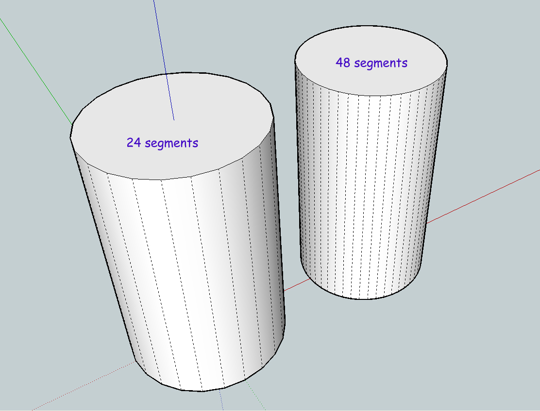
See picture above (I have hidden lines visible in this example):
I selected the circle tool and drew a 3" radius circle then pulled it up. That first circle was 24 segments which is the default. Next I selected the circle tool again but changed the segments to 48. You do this simply by typing the number on your keypad after selecting the circle tool. You will see your number displayed in the Value Control Box. It looks like this:
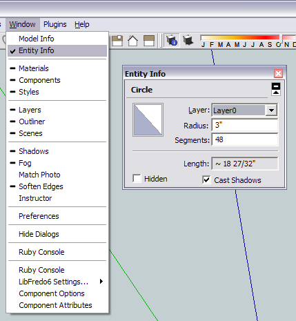
You can also change the segments of the circle (or arc) after you draw it but before you push/pull it. With the select tool select the circle and choose Window / Entity Info and you will see this box:
Now as for why you are seeing two circles in Autocad I am not certain, I don't have it here at home. My guess is that you are seeing a graphic issue. Do a refresh and you might only see the segmented circle. Can you select both?
Hope this helps.
-
Thanks for the reply. More segments makes smoothers looking circle true, but I'm not sure how those CNC machines will handle it. I mean, will it be smooth in real life (segments vs real circle).
It wasn't a graphic card issue. I can select both:
It looks like there are two lines in all round shapes. In sketchup when I view in wireframe mode, there's only one line.
-
I think I'm just going to replace all holes in my object with real circles in CAD. I think it's only solution to get smooth circle.
I have another problem with Arc. When I do Arc, it doesnt have straight lines. Here's picture:
Start and end points are from those guidelines:

Arc doesn't go to the points I wanted and is F'd up:

You can see that there's space between the Arc and "roof":

What is wrong with this?
-
It seems that Sketchup draws both Arc and segments for every round shape. You just can't see them in Sketchup, but you will see them in CAD.
-
That is odd because I am not getting that result when I export to Autocad. Now that I am at work I can check this on my end. This is what I am getting:

So how are you bringing it into SketchUp? I am curious as to why you have two "circles".Now the Arc problem. You must have some geometry issues going on. Can you post the model up for us to have a looky?
As far as accuracy with the CNC, you are probably best doing what you suggested, cutting new holes. That is unless you make your circles in SketchUp with a ridiculously high segment count. 96+
-
For your amusement I am attaching both the SketchUp and Autocad file I used above.
-
I opened your SU file and saved it as dwg and opened in CAD, same problem. You have to zoom close to see that extra line.

I do the drawing in SU and exported it as dwg so I can check how the dwg file looks.
btw, is there any way to snap object to the guide lines? My objects doesn't snap to any edge atm.
-
To me, it really seems that somehow while your segmented SU circle is transferred correctly to CAD, it adds one of those "real" CAD circles to it as well.
I don't know what the solution could be - only the images suggest this to me.
-
This is what I see in SU:

This is what it looks like after importing to CAD:

And this is how it looks after I select steering wheel tool:

So after I open the dwg, it has that very hard shaped Arc, but after I select steering wheel tool or orbit the image in some other way, the Arc changes so it's more round.
-
In AutoCAD type 'regenall' and see if that fixes it - it might be a graphics glitch ?
-
regenall makes it look like 2nd pic, but it doesn't fix it. It's not graphical glitch because I can select it. I think I'm just going to learn how to do the whole thing in CAD.
-
Well there is certainly something going on at your end. I am not getting those results at all. Can you post the dwg for us to see? Maybe post your export settings as well?
SketchUp does not calculate a true circle so you should not be getting this at all.
Edit: to upload the dwg just change the extension to zip or add .zip after dwg so it will upload.
-
If I'm not totally wrong, I think the solution is not too difficult.
A Sketchup circle or arc is not the sum of its segments (there are cardinal points and you always edit it later and change the radius). So my idea is that Sketchup has the low poly circle and a hidden real circle for editing the properties. Have you tried right click and explode curve? -
You can only edit the number of segments when the circle or arc is in 2d. As soon as you push/pull the circle you no longer have that ability.
-
I think dwg attachment is allowed - at least you can try before renaming it.
-
I tried before adding mine and it is not allowed.
Advertisement


