• Login
sketchucation logo sketchucation
  • Login
โ„น๏ธ GoFundMe | Our friend Gus Robatto needs some help in a challenging time Learn More

Autocad topography

Scheduled Pinned Locked Moved SketchUp Discussions
sketchup
23 Posts 6 Posters 2.4k Views
Loading More Posts
  • Oldest to Newest
  • Newest to Oldest
  • Most Votes
Reply
  • Reply as topic
Log in to reply
This topic has been deleted. Only users with topic management privileges can see it.
  • J Offline
    jalba
    last edited by 13 May 2009, 17:36

    Hi i'm a first time user of SketchUp.

    i did a survey topography plan using Autocad (with all the contours and what not) and wanted to get a 3D rendering. i imported the file, which resulted in multiple separate lines.

    is there a easy way to create a #d rendering, cause the time to redraw over each of the contours is very strenuous.

    Thanks in advance. ๐Ÿ˜’

    1 Reply Last reply Reply Quote 0
    • C Offline
      caddict
      last edited by 13 May 2009, 20:26

      this should be easy with draw > sandbox > from contours

      are you saying that what was a polyline in autocad appears as individual lines in su? the from contours tool is ok with that as long as the lines are actually connected.

      may help if you can post the .skp or at least an image

      1 Reply Last reply Reply Quote 0
      • J Offline
        jalba
        last edited by 13 May 2009, 21:34

        what i have attached is a sample of the situation i'm plagued with. I do get the separate faces, and with using push/pull i could create a step up for each face. My issue is to achieve a more flowing view of the land.


        sample- flat out


        sample - with step up

        1 Reply Last reply Reply Quote 0
        • C Offline
          Chris Fullmer
          last edited by 13 May 2009, 21:45

          Hi Jalba, Caddict gave good advice. Look into the sandbox tools. Make sure they are on - go to Window > Preferences>Extensions and turn on sandbox tools.

          Then you should see a new set of icons for the sandbox tools.

          Select the contours and then activate the "from contours" tool in the sandbox toolbar. It will place a smooth terrain over your blocky contours.

          If your contours are overly detailed, this could take a long time. So try it on a small test model first to make sure you have it working. then try it on the big model.

          Chris

          Lately you've been tan, suspicious for the winter.
          All my Plugins I've written

          1 Reply Last reply Reply Quote 0
          • G Offline
            Gaieus
            last edited by 13 May 2009, 23:19

            Jason,

            What you attached as "flat..." is really flat. I mean the contour lines are on the same height (z axis value). So first of all you need to "lift" (move) each one to the appropriate height so that the Sandbox can create a proper mesh. Otherwise it will also be flat.

            Gai...

            1 Reply Last reply Reply Quote 0
            • J Offline
              jalba
              last edited by 13 May 2009, 23:35

              so....no can do when i lift each face by the desired height huh, then smooth off?

              1 Reply Last reply Reply Quote 0
              • G Offline
                Gaieus
                last edited by 13 May 2009, 23:40

                PushPull will give you a staircase effect. Some (mainly physical) models use that so if you like it,go with it. As was said above, you need the From contours tool from the Sandbox to have a smooth mesh.

                Gai...

                1 Reply Last reply Reply Quote 0
                • C Offline
                  Chris Fullmer
                  last edited by 14 May 2009, 00:41

                  Hi Jason, please try the contour tools. They do exactly what you want. EXACTLY. Have you seen the multiple suggestions to try them now? thanks,

                  Chris

                  Lately you've been tan, suspicious for the winter.
                  All my Plugins I've written

                  1 Reply Last reply Reply Quote 0
                  • J Offline
                    jalba
                    last edited by 14 May 2009, 14:14

                    ok. i'm getting it now. thanks for the help ๐Ÿ˜„

                    1 Reply Last reply Reply Quote 0
                    • J Offline
                      jalba
                      last edited by 14 May 2009, 19:10

                      ok., now i'm getting a grasp of what i must do. But if you see attached the land boundary is not a perfect square. When applying the "from countours" command, the left hand side is not shaping well (looks like a big ditch).
                      What to do in this situation? ๐Ÿ˜•
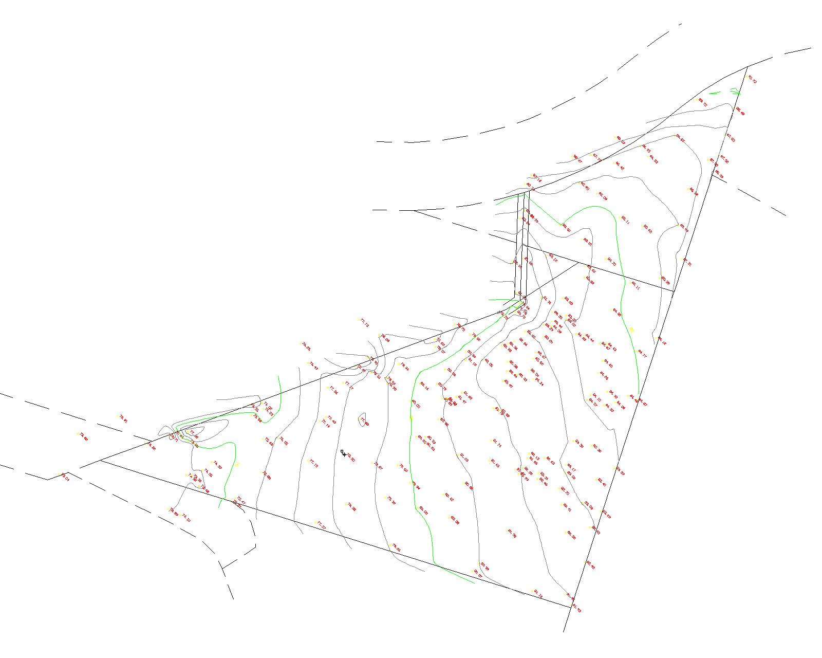

                      topography drawing

                      1 Reply Last reply Reply Quote 0
                      • C Offline
                        caddict
                        last edited by 14 May 2009, 20:26

                        difficult to understand the problem...can you post the .skp file

                        1 Reply Last reply Reply Quote 0
                        • J Offline
                          jalba
                          last edited by 15 May 2009, 12:09

                          Here's the file. Hope you could understand. The reason it is such in a irregular pattern is because the extreme outer edge represents the boundary.

                          When applying the command you suggested, i ended up with a big ditch on the left hand side of the drawing.


                          SAMPLE LAND.

                          1 Reply Last reply Reply Quote 0
                          • G Offline
                            Gaieus
                            last edited by 15 May 2009, 14:58

                            Note that you can always edit a mesh manually. Turn on hidden geometry to see all the lines making up the mesh, double click on it to edit and simply delete what you don't need (see attached example where I got rid of the extreme left edges - now definitely not in a political meaning of this extreme left ๐Ÿ˜„ ).

                            You can also make alterations in it with the Smoove tool (also from the Sandbox), outline buildings, roads and such with the Drape tool and create "terraces" or anything (for buldings, roads etc. again) with the Stamp tool.


                            Untitled-3.zip

                            Gai...

                            1 Reply Last reply Reply Quote 0
                            • J Offline
                              jalba
                              last edited by 15 May 2009, 17:18

                              guess i'll have to go by trial and error.
                              but...uhh....dumb question.....how to display hidden edges?

                              1 Reply Last reply Reply Quote 0
                              • A Offline
                                Anssi
                                last edited by 15 May 2009, 18:02

                                @jalba said:

                                guess i'll have to go by trial and error.
                                but...uhh....dumb question.....how to display hidden edges?

                                View menu>Hidden geometry

                                Anssi

                                securi adversus homines, securi adversus deos rem difficillimam adsecuti sunt, ut illis ne voto quidem opus esset

                                1 Reply Last reply Reply Quote 0
                                • G Offline
                                  Gaieus
                                  last edited by 15 May 2009, 18:30

                                  @jalba said:

                                  guess i'll have to go by trial and error.

                                  And step by step. Don't worry, it's the same for everyone at the beginning. You'll get it eventually.

                                  Gai...

                                  1 Reply Last reply Reply Quote 0
                                  • J Offline
                                    jalba
                                    last edited by 16 May 2009, 14:50

                                    ok...ew issue...
                                    i adjusted my countour lines on Autocad with each step up @ 1m. Checked a side view of it and everything was planar.

                                    When i import it however, some of the lines are sent off canter. Quite annoying!!!!

                                    How can i correct this?

                                    you can see the lines that are of canter by watching the side view. please not that each contour is at a 1m interval.


                                    henderson.skp

                                    1 Reply Last reply Reply Quote 0
                                    • C Offline
                                      caddict
                                      last edited by 16 May 2009, 20:14

                                      not sure what you mean by off canter

                                      first thought...in SU are you viewing in orthographic (camera>parallel projection)

                                      i guess you are refering to some of the contours sitting many metres above the main group.

                                      difficult to find an explanation for this...are these misplaced lines properly placed in the autocad file?

                                      1 Reply Last reply Reply Quote 0
                                      • C Offline
                                        Chris Fullmer
                                        last edited by 16 May 2009, 20:58

                                        I took the terrain and moved those stray lines straight down until they into the topography where I thought they would go (I could have mis-placed them). Then I ran from contours over the whole thing. And I tidied up the edge on the left by erasing some lines that were created, but not accurate.

                                        Take a look at it and see if that is about what you want.

                                        Chris


                                        henderson tin.skp

                                        Lately you've been tan, suspicious for the winter.
                                        All my Plugins I've written

                                        1 Reply Last reply Reply Quote 0
                                        • J Offline
                                          jalba
                                          last edited by 16 May 2009, 21:02

                                          hehehe you won't believe this but the reason those particular lines were offseting too much was because in the original Acad document, they were classed as 2D polylines instead of normal polylines!!!! lolz

                                          Exploded them and reformed them as normal polylines. Reimported and everything is back to normal.

                                          Thanks anyways peeps!!!

                                          1 Reply Last reply Reply Quote 0
                                          • 1
                                          • 2
                                          • 1 / 2
                                          1 / 2
                                          • First post
                                            13/23
                                            Last post
                                          Buy SketchPlus
                                          Buy SUbD
                                          Buy WrapR
                                          Buy eBook
                                          Buy Modelur
                                          Buy Vertex Tools
                                          Buy SketchCuisine
                                          Buy FormFonts

                                          Advertisement