HELP PLEASE - Structural Engineering question.
-
HI Guys,
Need a little help. Can you take a look at the attached diagram, and answer this for me:

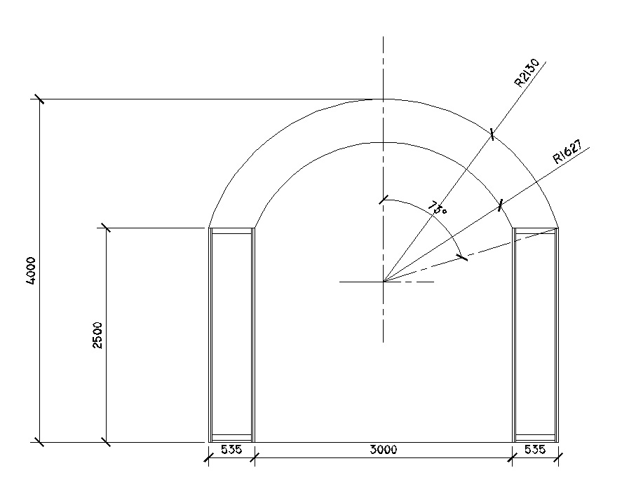
The diagram shows an arch, supported on two pillars. The arch is NOT a full half-circle, and as the diagram shows, the arch meets the towers at an angle of 73 degrees. The tops of the towers are horizontal. So, assuming the arch is securely fixed to tops of the towers, what percentage of the arch's weight is pressing down vertically, and what percentage is applying a side-ways force to the pillars. To make the maths simple, let's say the arch weighs 10kg (it doesn't really!)What are the loadings? Waaaaay out of my depth here, people!


All help is REALLY appreciated.
thanks,
Andy.
-
Without a lot more info we can't really tell...
Imagine for a minute that the arc of the arch is actually so 'flat' that it then effectively becomes a horizontal beam... then [assuming it is stiff enough to span ~3000mm at ~500mm deep*] then there is NO horizontal force on the pillars - each pillar supports half of the arch/beam. The load a beam will take without unacceptable deflection varies with it's material, cross-section/span, end-fixings, self-weight, loading etc. It's failure by 'shear' at the support is unlikely ever to happen as the 'deflection' of such a thin cross-section would be unacceptable anyway. *A typical timber roof or floor-beam spanning ~3m at 400mm c/c might be 150mmx50mm wide; a steel or r.c. beam carrying a typical roof or floor might be a similar depth (perhaps 'square in section). Thus a very 'stiff' arch [that acts like a beam] spans this ~3m easily without any sideways thrust...
Now image that the arch morphs into a pitched roof consisting of two sloping beams at ~45 degrees - the actual angle between the innermost bottom part of the arch and topmost 'apex'. If this roof has no 'collar' to tie it across it's base and the top apex joint is imagined as 'pinned' to allow free movement, then this does exert a a force sideways at the top of the columns... We simply imagine a collar that would restrain this force and find what tension force it'd be taking then [using the 'the triangle of forces' - Bow's notation], that is then the horizontal force that the top of the columns must withstand... Assuming the total weight of [and on] the arch is "10", with "5" as the reaction 'up' at each column. We could assume that half of the arch's downward load goes directly onto the columns at the bearing [2.5 each], therefore the remaining half is 'tension load' is taken horizontally - that's a total of 5, at each end [i.e. half of the load]... Incidentally the ~45 degree 'rafter' parts take a compressive force of 5 x ~1.414 each - say ~7.1...
So what is it then - a very stiff beam-like arch with little or no sideways force [e.g. it's made from steel or r.c.] OR a very weak arch that exerts sideways force [e.g. loosely laid stone-blocks with no masonry above them to hold them in place] ?
-
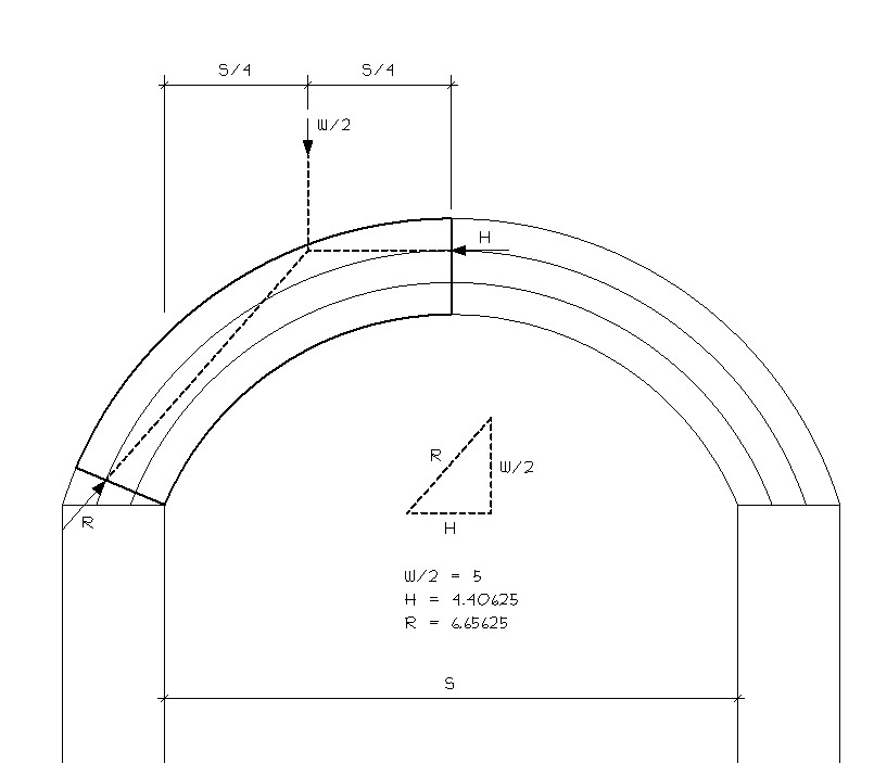
Andy, that's an interesting structural design question. After consulting the Technical Notes from teh Brick Insitute of America on arch design, my head is spinning. Analytically, there is no easy formula to calculate what you ask, but there is a fairly easy graphic method for calculating the horizontal thrust and reaction, using the hypothesis of least crown thrust: the thrust (H) at the crown is horizontal and passes through the upper 1/3 point of the arch; the reaction (R) passes through the lower 1/3 point of the arch at the skewback. (this assumption works for symmetrical arches symmetrically loaded only).
Since the arch is symmetrical, you only need to calculate half of it. W = equivalent uniform load. The load is more than just the weight of the arch itself, but for simplicity, I used the 10kg you mentioned. After determining the direction (angle) of the reaction by connection the lower 1/3 point of the arch to the intersection between H and W/2, draw a force diagram to scale, with W/2 = 5.

-
Hi Guys. Really appreciate the quality and depth of your responses. A little more detail if it helps: This is for a trade-show stand. The arch is constucted from from two MDF profiles, skinned with plywood to form a box-section. The supporting pillars are aluminium framed structures. The tops of the pillar frames contain an mdf plate, to which the arch-ends are screwed. Originally the arch was to have been a full semi-circle, but a restriction on-site prevents this. So the plan now is to build as per my earlier drawing. The concern is whether this non-semi-circular arch will apply a spreading-load to the pillars (which cannot be secured to the floor). Ultimately, we'll build this in our workshop to assess it before installing on-site. I'm just keen to understand the forces at work here!
EDIT: TIG you replied as I was typing. The arc is wholly rigid, so would, as you say, function like a beam. What you wrote makes a lot of sense. Thank you.
A.
-
IF the arch were made of completely stiff stuff - like well reinforced concrete - it'd act like a beam and then it'd exert NO horizontal forces at all - it depends what is what...
Make it out of kid's building blocks...
Glue the blocks together = no force
Balance the blocks = max. force -
@andyc said:
Hi Guys. Really appreciate the quality and depth of your responses. A little more detail if it helps: This is for a trade-show stand. The arch is constucted from from two MDF profiles, skinned with plywood to form a box-section. The supporting pillars are aluminium framed structures. The tops of the pillar frames contain an mdf plate, to which the arch-ends are screwed. Originally the arch was to have been a full semi-circle, but a restriction on-site prevents this. So the plan now is to build as per my earlier drawing. The concern is whether this non-semi-circular arch will apply a spreading-load to the pillars (which cannot be secured to the floor). Ultimately, we'll build this in our workshop to assess it before installing on-site. I'm just keen to understand the forces at work here!
A.
IF the boxed sheet structure is rigid then it's a box-beam - NOT an arch... Beams exert NO horizontal forces.
Would one sheet of ply try to spread sideways at its ends ? If the answer is 'NO' then there are no forces... Two sheets of ply boxed into a 'beam' = even less problem...
IF you had been stacking up loosely laid plywood boxes to form the arch that's another kettle of fish...
-
As TIG says, if the arch is rigid then the loading on each column is half the weight of the arch. If the arch is non-rigid and sags under its own weight then the columns will be pushed apart. Frankly, I would be more concerned about the thing falling over and flattening a few people. How are you going to stop it falling out of plane?
If you are still worried then you could tie the ends of the arch together using architectural rigging http://www.architecturalriggingnorthwest.co.uk/wirerope.html
Regards,
Bob -
Hi Bob. The towers are tied back to other structures, but not in a way that would counteract the (non-existent!) sideways forces.
Once again guys, thanks for taking the trouble to respond to this. Think we're all sorted now

A.
-
Hi Andy and all.
Andy, I'm a fan of your work and I'm always interested in what you are going to show next, so glad to help if I can.
I have a little knowledge of structural engineering as my background was manual drafting of reinforced concrete and structural steel. I can't do a calculation for you but my two pence worth would be:
I agree that half the weight/force of the arch will come down upon each upright, though the arch should self-support. There may be a little spread at the "feet" of the arch, but the secret lies in the quality of the connections to the columns. Lateral restraint is also paramount, but you mentioned this, saying that the arch/columns would be tied back to existing in situ structure. Again, very important are the connections and restraint; we would overcompensate a little with bolt sizes and fillet welds just to build in a little extra safety factor.
Hope it helps in some small way.Cheers,
Nigel
-
Either I'm a little dense tonight (which is ALWAYS a possibility), or ...
If the tower(s) above the arch are at least the width of the columns, this should work as a conventional header spanning between two posts and the arch is simply added under the horizontal beam. Simple span, simple calc ... what am I missing here? This should be even more true if it's only a trade show booth - basically no loading other than the weight of the materials that it's built from.

Advertisement


