Intersecting group things with other grouped things
-
Ok, so we've got a situation like this:

Open the wall group and draw a rectangle around the beam:

Move a copy of that rectangle to the other side of the wall:

Select the 2 rectanlges and íntersect with model and delete the old rectangles:

You could also get this working within the beam groupby jsut sectioning of part of the beam and intersecting it.
-
Another quick idea for what you could have done to speed the whole thing up: after youd done one intersection you could ahve radially arrayed it and then just gone round and deleted the excess.
-
@caddict said:
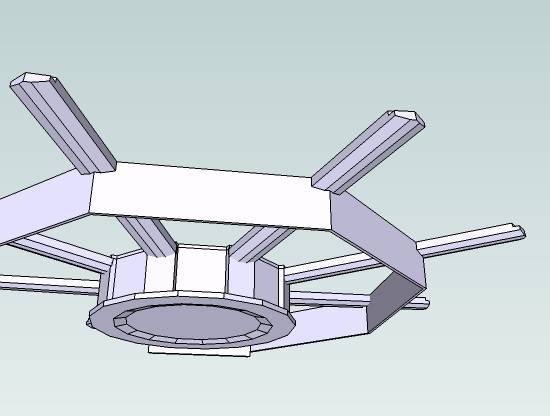
Thanks Remus, that method works in simple cases. Here is a portion of the model to give a better idea. Two of the cuts have not yet been made.[attachment=0:34eplysp]<!-- ia0 -->[attachment=0]wall beam cut.jpg<!-- ia0 -->[/attachment:34eplysp]
caddict,
I had a look at your model. Aren't you better of modeling just one core wedge containing top wedge and bottom wedge? And then just one beam? So you would have three components (not groups) all alligned along red in plan view.
Once you have them ligned up properly do the intersect selected.
The intersection will be just a few edges outside the three components.
You can now select the needed edges, copy them using the copy button, enter the component and do a 'Paste in place'. For each three components you need to do this (with the right edges). And each time delete the unwanted geometry afterwards.
Once done do a rotate/copy array having the three components selected, over 45 degrees *7.This will give you the beams and core as you want them.
The inner edges of the core wedges you need to hide.
(one advantage of having components)b.t.w. Your model has a lot of inaccuraties in it. Zoom in and you will see.
(beam<>core)Also the beams are slanted in two directions. One is obvious the other hardly detectable!!! but it is there. These things will eventually cause problems.
Wo3Dan
-
I've been moving the two groups along an axis (usually blue) a typed and remembered distance. Then I copy/move them both again. Now I can open one group in the first and intersect with model. Then the other group in the second and do the same.
Now I delete the unintersected groups, edit the remaining as I choose, then move all back to it's original position in the model. Goes pretty fast and without unexpected results...but I too am listening for a better way?
-
Thanks Remus, that method works in simple cases. Here is a portion of the model to give a better idea. Two of the cuts have not yet been made.[attachment=1:u1vn1rc0]<!-- ia1 -->[attachment=0]wall beam cut.jpg<!-- ia1 -->[/attachment:u1vn1rc0]

-
Yes Remus, definitely a good idea assuming perfect geometry. Wo3Dan, your idea about building the core in wedges is sound. Could the junctions between the wedges be hidden?
One of the main problems here is that I am building the model from 2d drawings which I thought were exact but which, it turned out, were not. I just imported profiles from the 2d drawings into SU. So now I'm having to go through the whole model (what's posted here is just a fraction of the building) correcting geometry.
I've replaced the original model on this thread, with a new (hopefully) corrected version.
Wasn't sure what you meant about
@unknownuser said:slanted in two directions
. Maybe it's corrected now.And Tom, I like your idea of getting the groups out of the model and working on them at a distance. What do you mean when you say "open one group"? Do you mean explode?
Maybe there is no "easy" way. At least there are options

-
caddict,
@caddict said:
.......................Wo3Dan, your idea about building the core in wedges is sound. Could the junctions between the wedges be hidden?
You can hide the edges of the wedge top face so when you do a 'Rotate/Copy' all the components join nicely and you will not see their 'mutual' edges in that face.
You only need to hide a few edges since you work with the component.
Adjustments later on will also be done in just one top wedge component, one bottom wedge component and one beam component.@caddict said:
.......I've replaced the original model on this thread, with a new (hopefully) corrected version.
Wasn't sure what you meant about
@unknownuser said:slanted in two directions
. Maybe it's corrected now.......It is better but the beam is still slanted in the tangential direction. (see attached file):
edge A = 118,539637mm
edge B = 118,549667mm
Not that much difference but these little differences (can) cause trouble later on. And it's so easy to avoid. Rotate till horizontal.Wo3Dan
![wall%20beam%20cut[1].jpg](/uploads/imported_attachments/vbnW_wall20beam20cut1.jpg)
-
Steve, I mean I open the group for editing (right-click menu or double-click), that way the intersected lines arrive inside that group. I'm using SU5, and maybe it's different in SU6, but I have to use the two sets of groups to get the intersection to happen inside both (i.e. do one then the second will say "no intersections" since they are already in the first).
-
OK, got you Tom. That method is probably the best we have since
@unknownuser said:the intersected lines arrive inside that group.
It seems that the faces created by the cut are not formed and must be done manually.
For interest's sake, the following method produces a result where the new faces are formed:
open group 1. select all geometry and copy. open group 2 and paste-in-place. while still selected, intersect-with-context. delete unwanted.
And Wo3Dan, thanks for your sharp observances...that will save me some trouble later!
-
Have just accidentally discovered a very cool enhancement of Tom's method.
This method assumes you only want to cut one of the grouped objects, which I find is often the case.
The skp shows how.

-
Good tutorial caddict.
That is a pretty good way of achieving that, thanks guys. -
Hi
May I offer a different method of setting up some of your intersecting components. Attached is skp with your component66 now called beam66. When you setup the component, in dialog edit the axis to layout along your beam. I have also setup an attached component on the beam66 called joint which aligns with the intersection of your central housing.
Keeping the joints and intersections in place allows you to move it into copied positions easier. When all the beams and joints are copied and in the right position then by double clicking one beam then clicking the joint and deleting it, it will be removed from all components at the same time...
We use this method when designing timber frame joinery.
Hope it helps.
-
Thanks for that Irv. I like the idea of having the joint as a separate component.
Advertisement


