TIG
Once again, thank you very much, you have been a great help.
TIG
Once again, thank you very much, you have been a great help.
Thank you all very much, TIG especially.
If it is the case that the example from the book is wrong and I am right, I am disappointed, with the book that is.
Can I ask though, why can I not calculate the shadow point onto the sloping roof of my drawing using the elevation drawings? I know how to calculate shadows on incline planes in multiview drawings using a section and an elevation. Can't I then find the coordinates of the point on the axial lines and do the same on the paraline drawing?
I used the triangle method, (TIG's method) and also used sketchup as you can see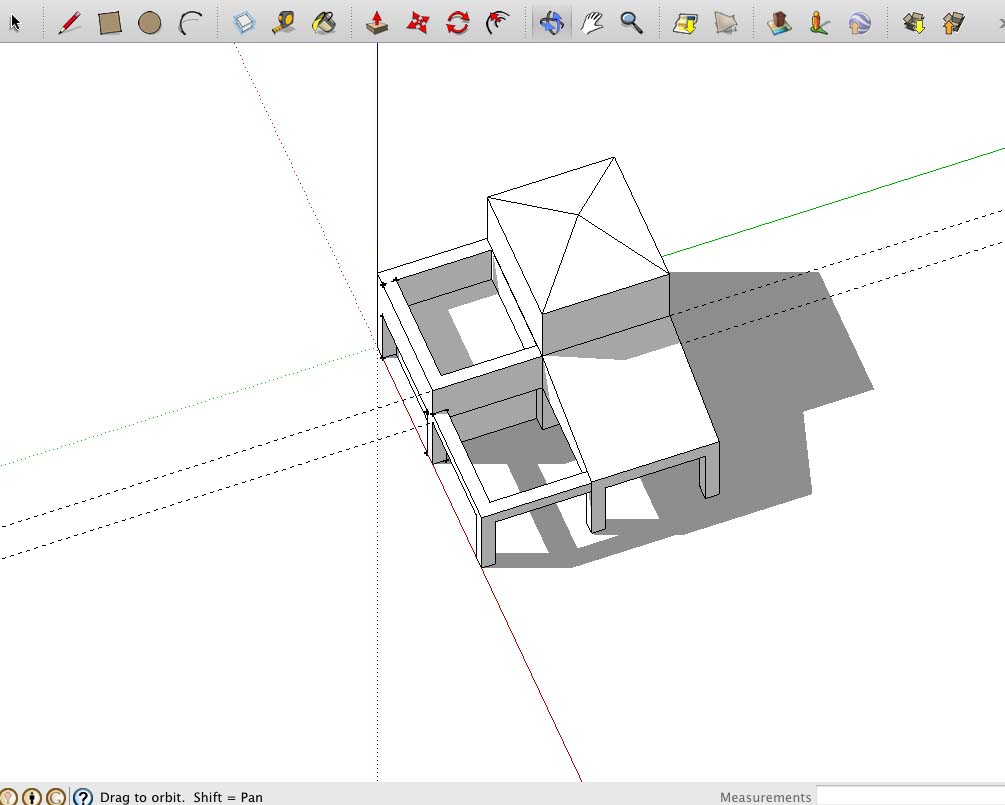
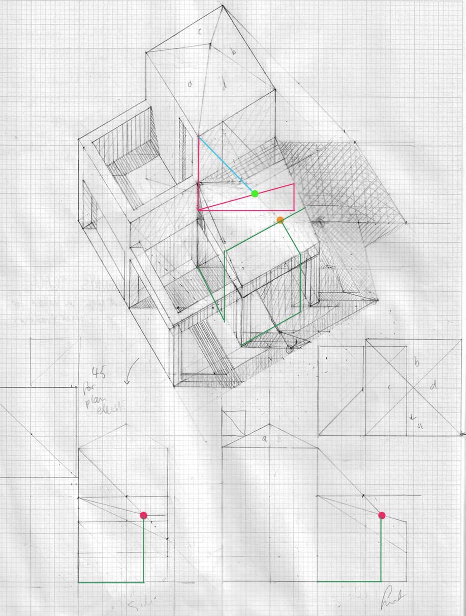 and it seems that I was right with using the triangle method, but why doesn't using the elevation co-ordinates work?
Many thanks again.
Elis
Thank you for the reply. I see your lines and understand them from the drawing, but how did you arrive at them?
The above 2 examples I attached show that the shadow lines are not parallel with the incline, so why is it the case with the last example.
I am confused.
HI everyone
I have a couple of questions regarding architectural drawing.
I am a full time artist and have started studying the above along with design drawing. I do not attend any university or college but am using 2 good books, namely, Frank Ching's Design drawing and Rendow Yee's Architectural drawing. I have also started using sketchup to try and solve problems that I cannot resolve by drawing alone.
The main problem I have now is from calculating shadows on inclined surfaces.
Please find below 2 examples from the books I am using that show the traditional method of calculating shadows by using triangle slices parallel to the picture plane from the point where the bottom of the object casting the shadow and the inclined surface meet.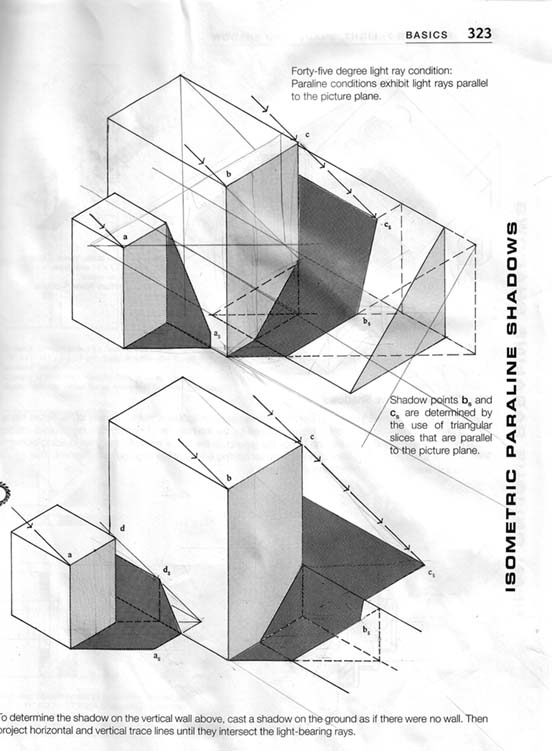
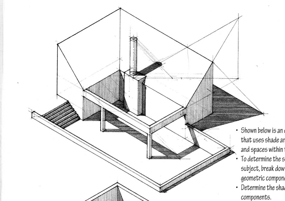
These both I understand. They are both also 30 degree isometrics. I don't know if this is the reason it works, though I doubt it as I have found that concepts and principles for paraline drawings, so far, are consistent across the board.
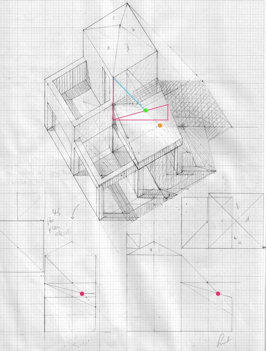
Below is the example which I don't understand and another picture of how I would calculate the shadows. The critical points for my shadows are the green dots .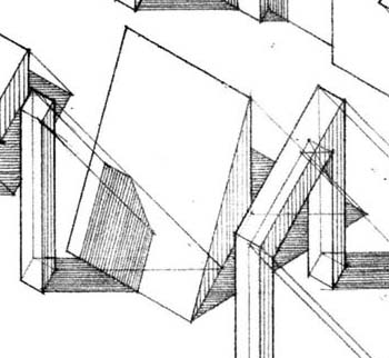
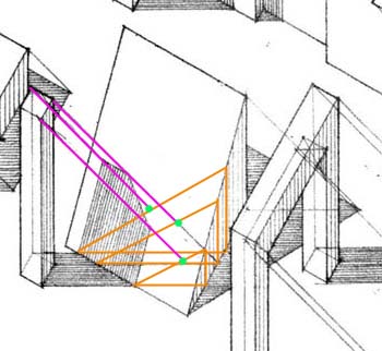
Could someone explain how the shadows from the example are arrived at.
I have also attached a drawing I made from a wireframe exercise in one of the books.
I tried to calculate the shadow point using 2 elevations. I have found calculating shadow points on inclined surfaces in multiview drawings much easier. I am pretty sure the result is correct but the resulting shadow point seems much further down and to the right of the multiview drawing then on the plan oblique. The pink dots are where I calculated the shadow points by using elevations. The green dot is where I would place the shadow point using the triangle slice technique and the orange dot is where the elevation shadow would be on the plan oblique by using axial line measurements.
I really hope someone can help me out on this, I have wrecked my brain over this for 2 days!
If this is not the appropriate forum or venue, apologies, and if anyone could otherwise point in the right direction for some help online I would really appreciate it.
Many thanks
Adam
