First class and beyond. 


Posts
-
RE: Weld beads, frayed ends & ribbon
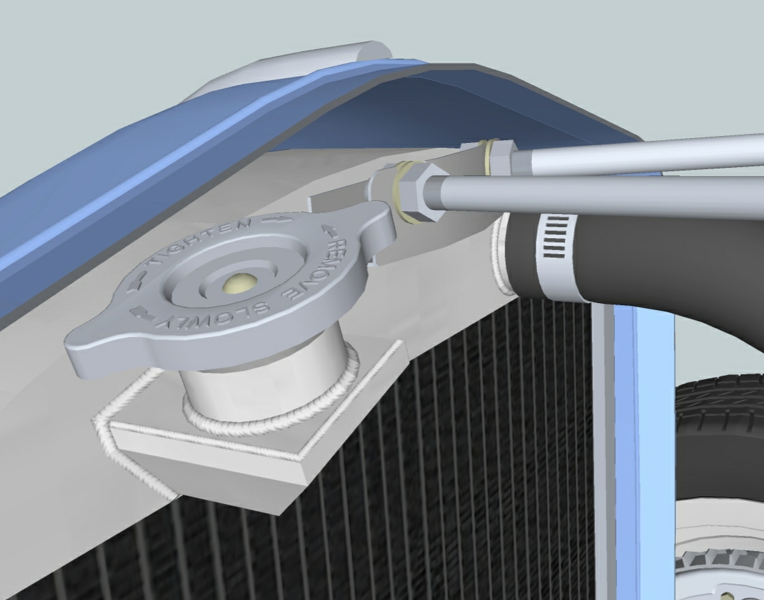
Making progress on the welds. Found a suitable jpg image of a weld bead, edited it for color, contrast and brightness. Also straightened and cropped to allow clean tiling. It is a tedious process to get the texture correctly sized and aligned to each facet. I size the texture to fit one tile to the facet width without much texture overhang. If I oversize the tile too much I loose detail at the outer edges of the resultant bead. This positioning process would be easier if the size and rotate tools within texture position were separate instead of combined.
-
RE: Munster Koach
Steve,
I have to do the line at a time thing to. Very time consuming.
Did you download the '32 from google docs?
Just saw your new roadster - Sweet. Because the car is so small any abrupt change in contour will cause a lumpy effect. Might try making the side (vent) indentations shallower???
Jim -
RE: Munster Koach
You are very sick and very taleted.

How long did it take you to build? I'm very impressed.
Jim -
Weld beads, frayed ends & ribbon
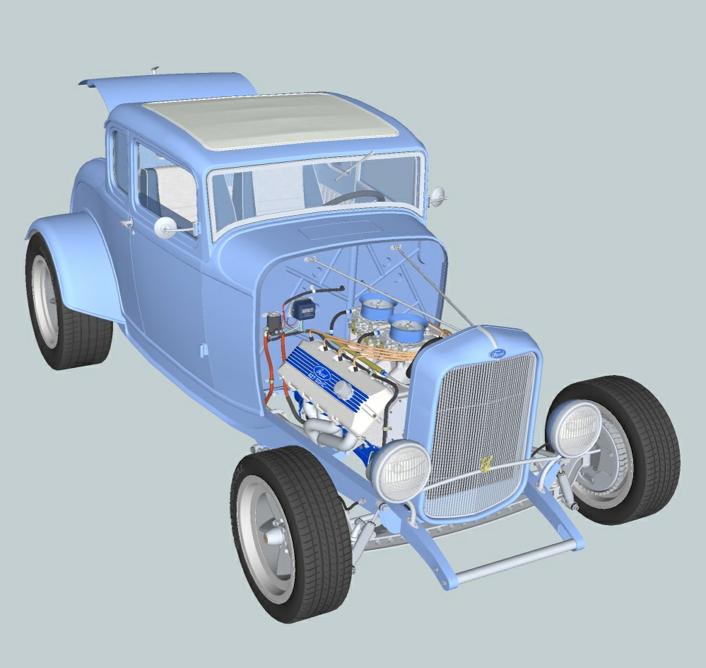
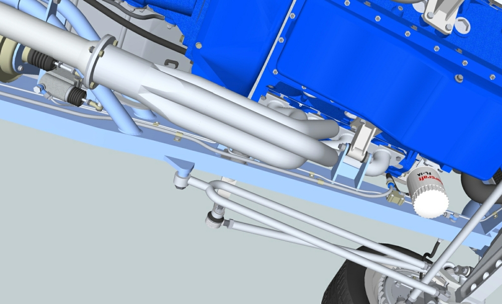
I'm adding final components and detail to my 32 Ford project and need some advice. Are any of you aware of a method for creating realistic weld beads in SU? Possibly a plug-in. In the first image I would like to dress up existing and add new welds to the aluminum radiator. Second image shows the undercarriage and endless possibilities for welds at the frame joints.
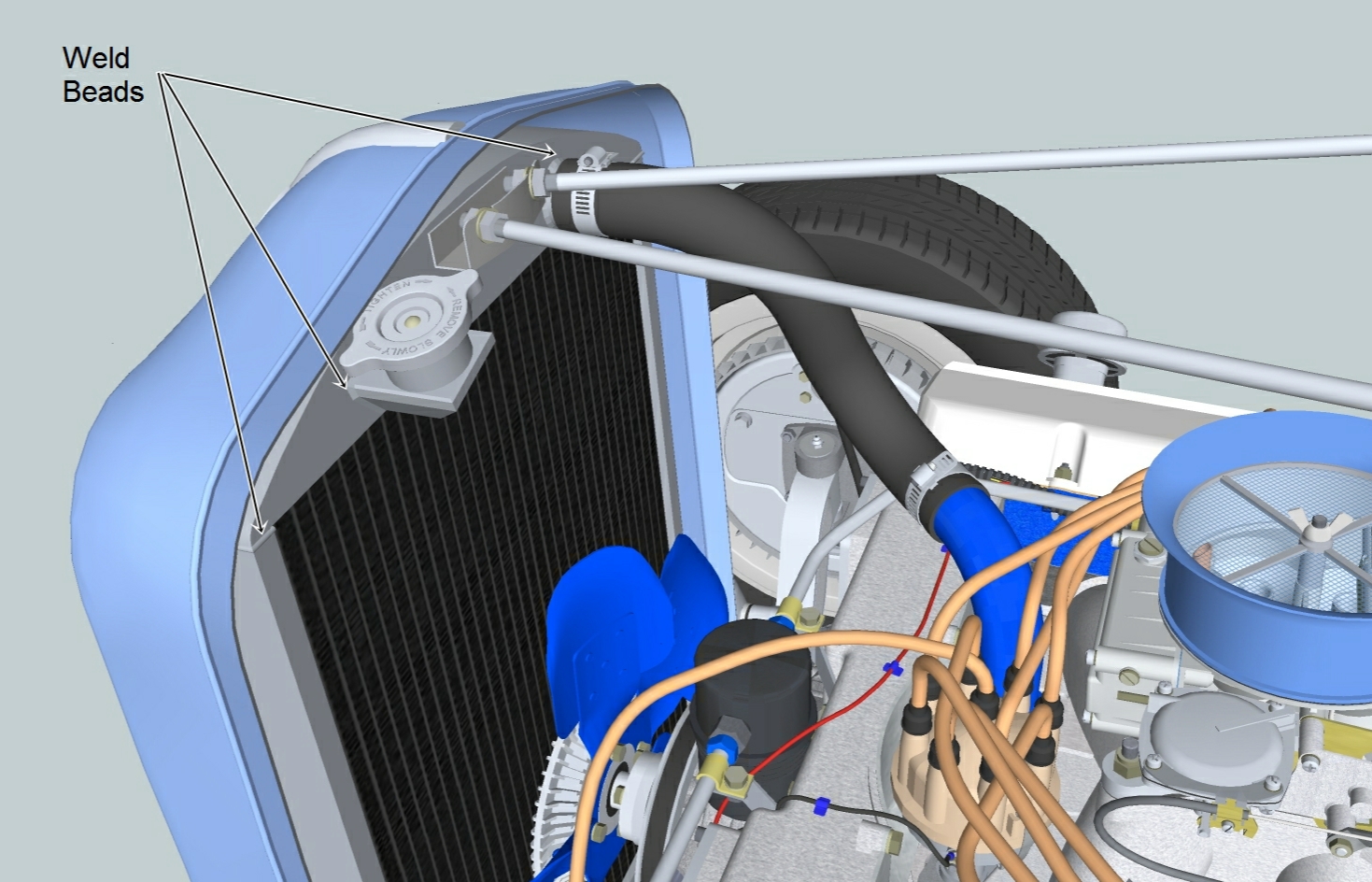
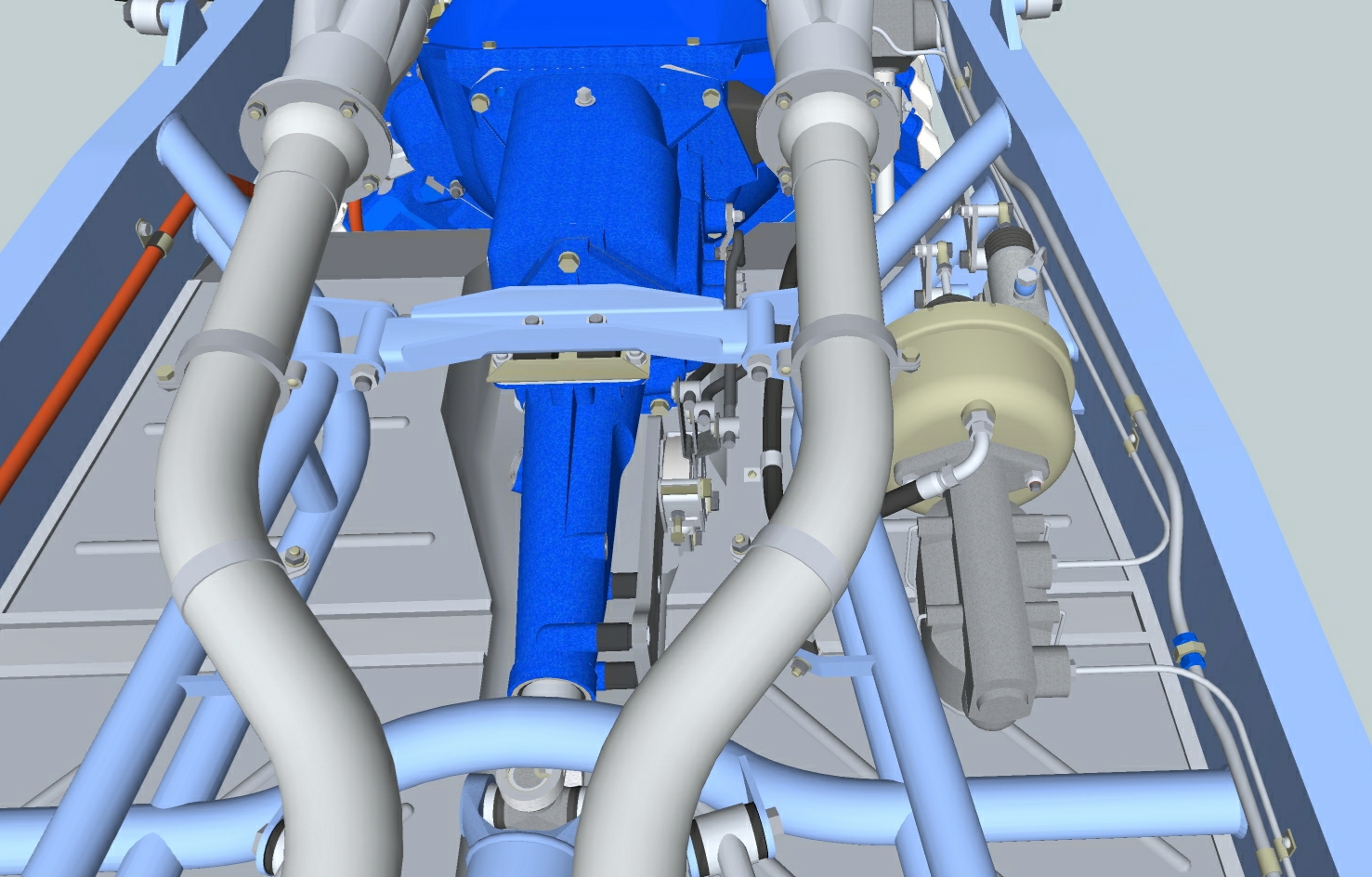 There is a protective fiber sheath covering the lower portion of the cable running from the starter relay to the starter. As shown in image 3. I would like to make the end of this sheath frayed. Any ideas?
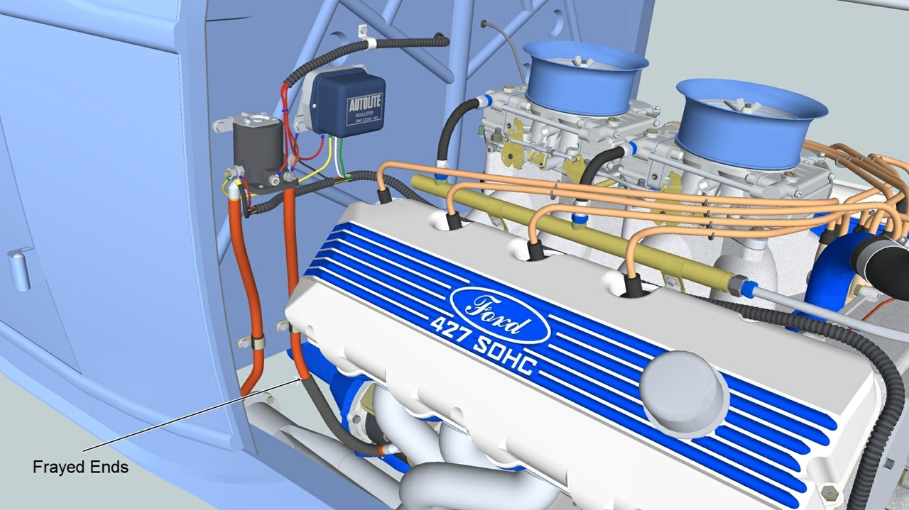
I struggled to create the seat belts you see in image 4 and am not overly pleased with the results. They look too stiff and mechanical. They should flow smoothly like a ribbon freely dropped into place. This is easier said than done due to the bulging and dipping shape of the fabric as it changes direction. Help!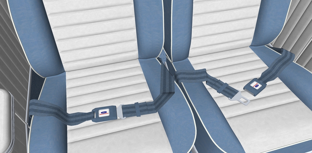
Also, do not hesitate in offering your criticism of all else that you see in the images. It is still a WIP with some known clean-ups in process but would really appreciate the input from this very talented pool of individuals.
-
RE: Check out this extremely talented modeler
@hellnbak said:
I hate to point this out, but I think one of the head gaskets is about .0000000001" too thick. Ruined the whole model for me.

Rechecked the head gasket thickness and they are both within Fords' spec. tolerance range. You need to get your measuring devices re-calibrated and/or start using your good eye.

On a serious note, I stumbled upon a situation that causes me great concern. While surfing for project reference information, I found a Ford 427 v8 SOHC 3d model for sale on TurboSquid. My model being sold by someone else. I have had this model posted on my Google docs page as a shared file (my bad)for about 6 months. In the future, any sharing I do will be on an invitation only basis. I really enjoy seeing others utilize my models in their projects, but openly advertising and selling them in original state is not acceptable by me.
What have the rest of you experienced along this line and what are your opinions?
JMJ-Ohio
-
RE: Check out this extremely talented modeler
@urgen said:
....JMJOhio,Thanks once again!

...some edit model for render...fast Hypershot+photosnop....
....

[attachment=0:3cgd8z0y]<!-- ia0 -->accu.jpg<!-- ia0 -->[/attachment:3cgd8z0y]Thank you urgen. Great rendering. Can you offer any suggestions/recommendations relative to the model creation process that would reduce the render efforts, (preparation, render specific set-up and post editing) and still offer the best final image. A very broad question and looking for simple answers. Structure, organization, applied materials, imported images, etc...
-
RE: Check out this extremely talented modeler
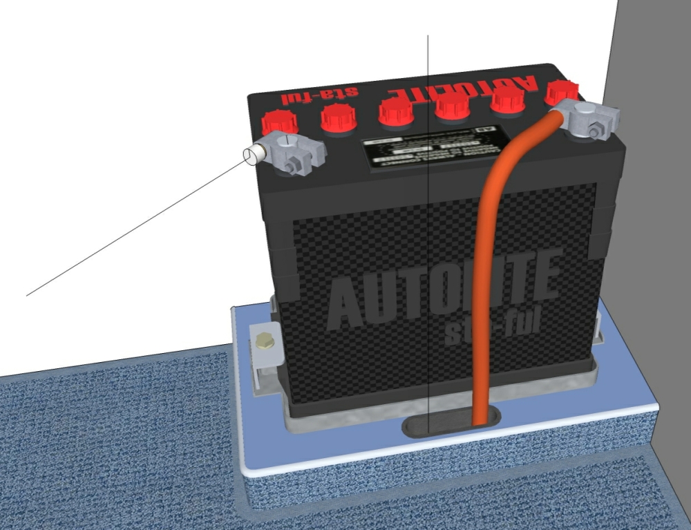
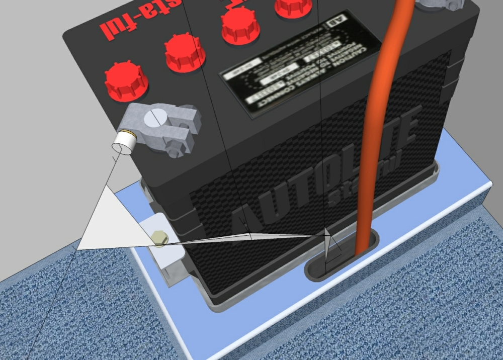
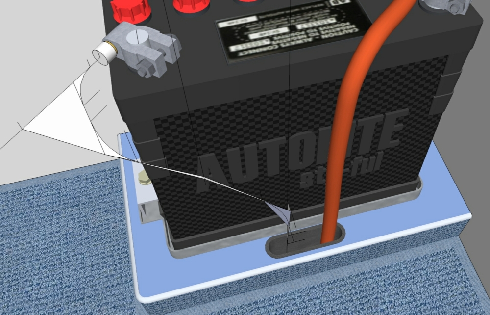
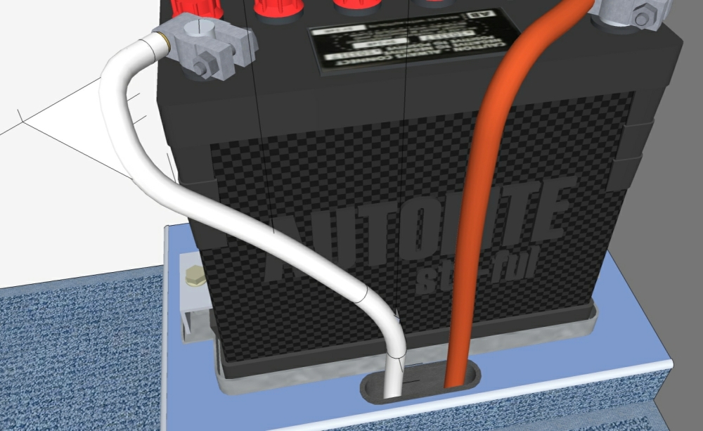
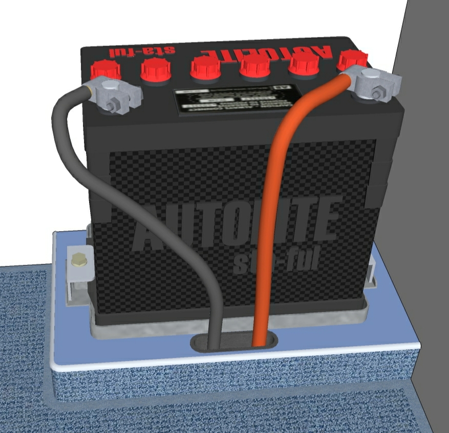
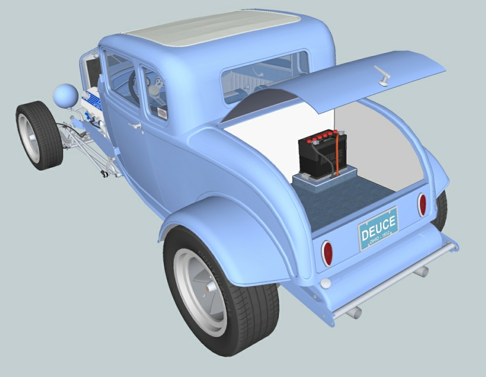
I was in the process of creating cables for the trunk mounted battery in my 32 Ford when you posted this question. Had one finished and ready to start the other. So I saved some screen captures as I created the second one.
There are two threads in this discussion. The first one is subjective and pertains to the real life behavior of the items you are modeling. I rely on intuition and reference photos while creating a path for the entity. I use the same methods for modeling wires, pipes, lines and hoses but think differently as I develop the paths for the varied materials. Exhaust pipes, fuel lines, brake line and etc. are rigid and retain their mechanically formed or fabricated shape. Hose is semi-rigid to flexible, depending upon type of material and diameter. It is fairly predictable, but you must be conscious of minimum bend radii and sag in between supports. Wire is the most unpredictable and difficult to path for. Heavy gauge, stiff wire behaves like semi-rigid hose, but will have small random kinks in it. Softer, lighter gauge wire starts behaving like a wet noodle.
The second discussion thread is objective and relates to construction methods and tools used or not used. Eric's CatchUp tutorial is very good guidance. I use a network of lines and planes for my guide construction and then finish the path with tangent arcs instead of splines. The wording of your question leads me to believe that you are not using splines or arcs, just line segments. If that's the case, I understand your difficulty with the 3d construction and lack of predictable results. The splines and the way I construct my arcs creates tangents at each intersection and a resultant smooth flow. My network of lines and planes allow me to maintain control as I bridge 3d space between A and B. Try both methods and see which works best for you. I have not tried "pipe along path", but will take a look at it.
-
RE: Check out this extremely talented modeler
Very good point. I have been using more sub-components lately, but your example breaks the final component into more chunks than I would have created. Thanks.
I also need to break the habit of using to many arc and circle segments when they are not necessary. -
RE: Check out this extremely talented modeler
I think your center of gravity is to high. They look a little bit roll-over prone.
I'm in Brookville, northwest of Dayton.
I followed drag racing pretty closely during the 60's & 70's and this engine made it's presence known. NASCAR banned it and NHRA loved it.
The detail. As mentioned earlier, OCD runs in the family.
-
RE: Check out this extremely talented modeler
Hello Everyone...
I'm JMJ-Ohio (Jim Jeffries) and I live in Brookville, Ohio. I want to thank hellnbak for introducing my work to this forum. Did'nt know SketchUcation existed until he contacted me. The "Cammer" was my first real project using SketchUp and I relied more on countless hours at the tube and stubbornness than on talent. The monkey can paint a masterpiece if given enough time and bananas.

I have been involved with machinery and mechanisms for 40+ years, being employed as a mechanical designer and project engineer. I retired 2 years ago, thus allowing me time to catch-up on home projects and play on the computer. But, I rejoined the work force last month so play time will now be very limited.
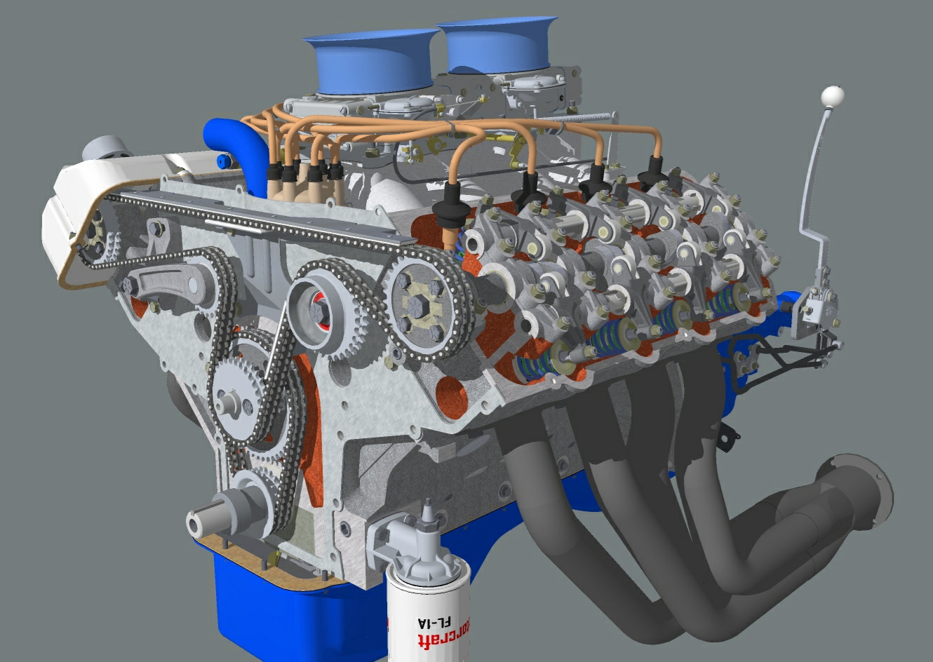
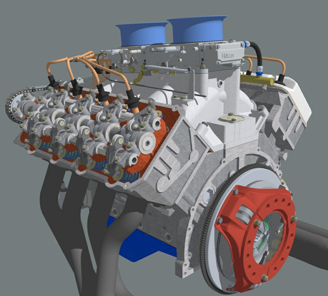
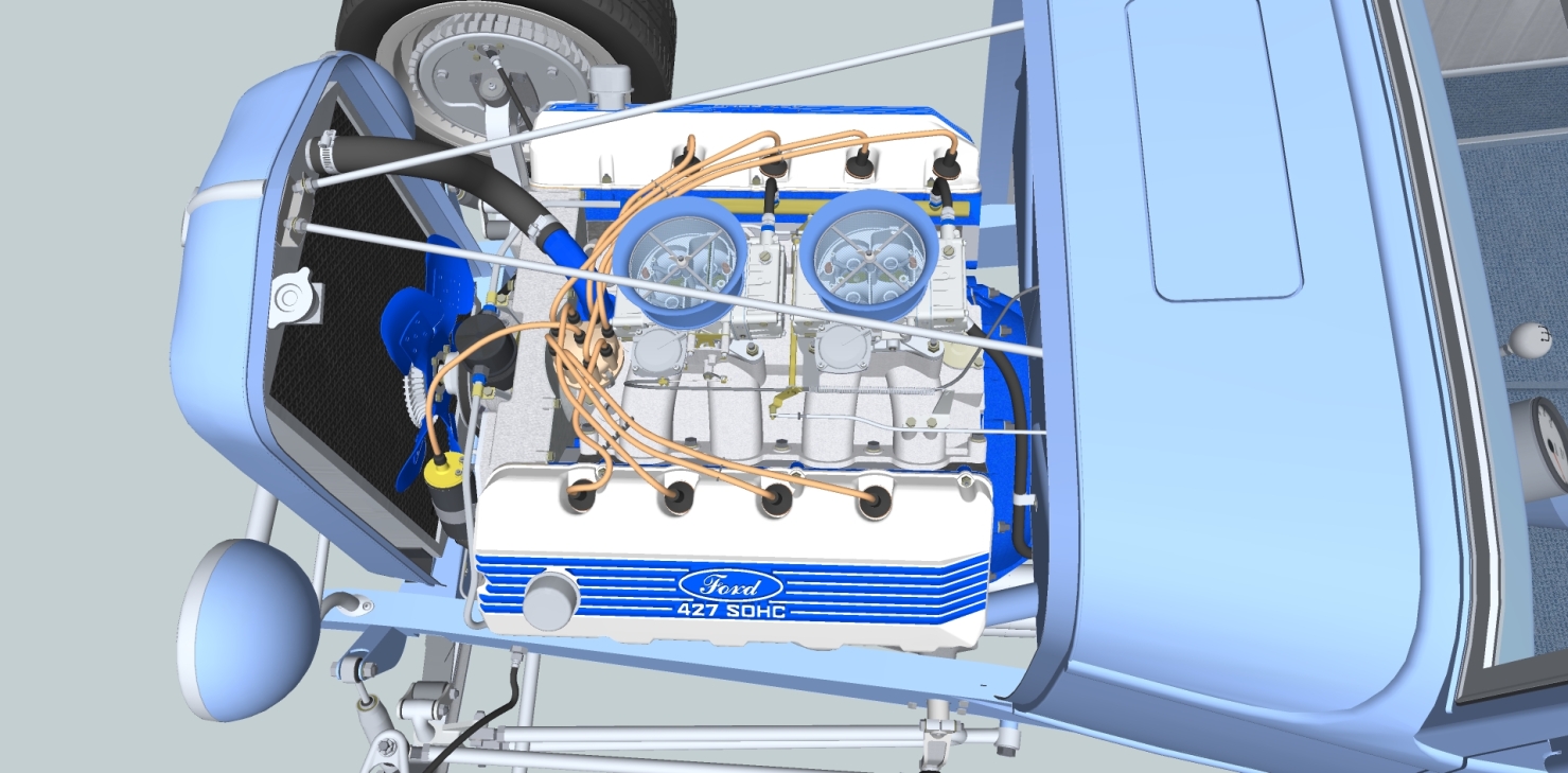
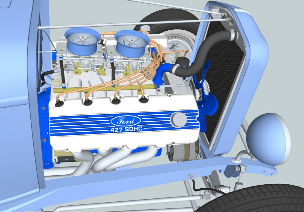
The Ford 427 SOHC project. No, I didn't have any blueprints or have an engine in my garage. Online research netted numerous technical articles that included critical dimensions and data. I also downloaded and printed hundreds of photos. The combination of known dimensions, proportional measuring of photos and deduced dimensions via detail relationships allowed the picture to come together. A thorough understanding of the function and construction of the subject item is a vital part in allowing the creation of realistic images.
I am pleased with the results of my efforts, but my models are not practical due to their resultant file sizes.
I envy those of you who can create works that please the eye, are portable in size and don't take hundreds of hours to produce. There are many very talented artists and craftsmen out there and when I see their work it encourages me to try harder and learn new ways to do things.Have added a few more screen shots.
p.s. -- no bolts from the top in those carb holes. Your second observation is correct.
