sketchucation logo sketchucation
    • Login
    1. Home
    2. 94JZA80
    3. Posts
    ℹ️ Licensed Extensions | FredoBatch, ElevationProfile, FredoSketch, LayOps, MatSim and Pic2Shape will require license from Sept 1st More Info
    9
    Offline
    • Profile
    • Following 0
    • Followers 0
    • Topics 7
    • Posts 35
    • Groups 1

    Posts

    Recent Best Controversial
    • RE: Complex dynamic components - slow...

      @pcmoor said:

      for doors use flip along axis instead of using a left and right component.

      i understand the "flip along axis" concept you speak of, but i have no idea how to implement it in the sub-component of a dynamic component (such as the door on a dynamic cabinet). for instance, i'm currently using the latter method you mentioned (i have two door components, one left and one right, and the left door stays hidden when the cabinet is "hinged right," and vice versa). i would love instead to use a single door that can be hinged either left or right. but when i try to do that, i get door rotation and door location issues.

      W1D.skp
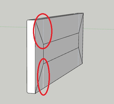
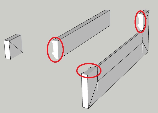
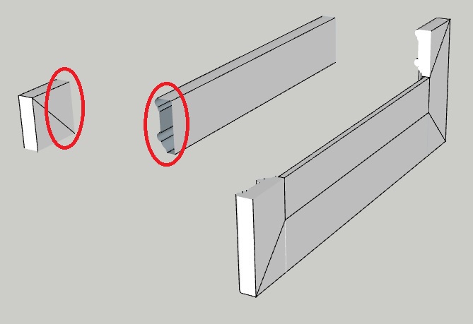
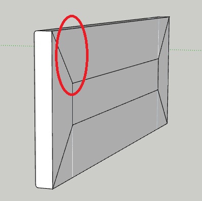
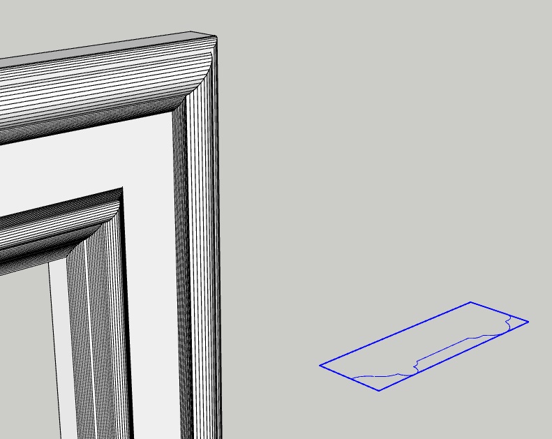
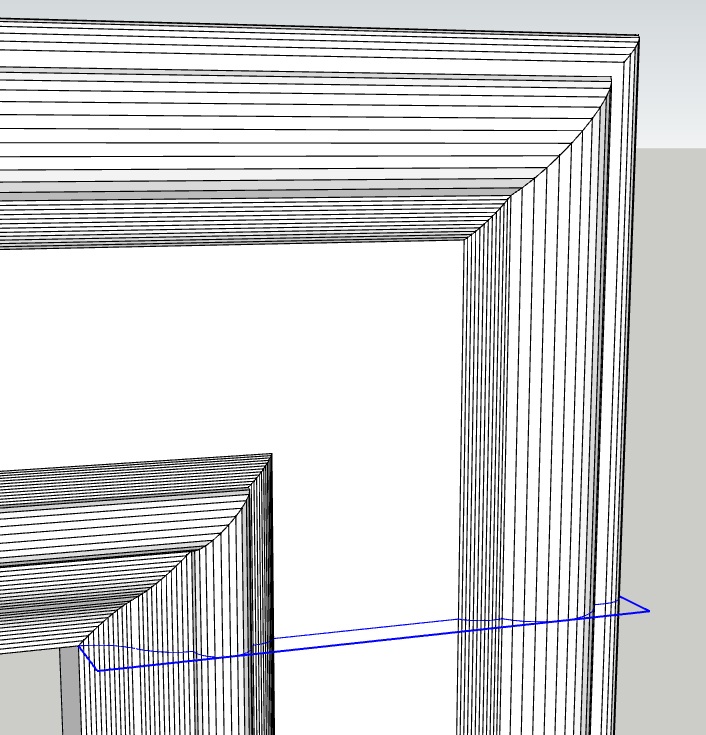
      above is a single door wall cabinet (designed by Exitenz) that i found in the 3D Warehouse, and it uses only a single door component that can be hinged left or right (as opposed to using two door components like i did, and keeping one of them hidden at any given time). the door position and rotation formulas make sense to me when i look at them in the component attributes window, but only if the door's component axes change when the hinging changes from left to right or from right to left. in other words, his door must work as hinged left and hinged right b/c it flips along an axis whenever the hinge selection is changed...and this is what i'm having trouble with. the only way i know how to perform such an action is to right-click on a selected component and use the "flip along component's red/green/blue" function. Exitenz's wall cabinet does this automatically when the hinging gets changed from right to left or vice versa...play with his model and see for yourself. anyways, the reason i get door position and rotation problems in my own model is b/c my door's component axes don't reposition (due to a flip along a particular axis) upon a change in door hinging. how do i go about this? here is my model so you can see what i've done so far:

      W1D_one_door_swing_both_ways.skp

      @pcmoor said:

      for rotating function, you need to place an extra component wrapper to protect contents

      i'm not entirely sure what you mean by this. are you saying that component that is meant to rotate (such as a cabinet door) must be a grandchild to the main component (the cabinet itself)? Exitenz's model above had a component wrapper <F_W1D> around the actual door component <DRBB#1>, making <DRBB#1> a grandchild of the actual cabinet <W1D>, and i don't quite understand why that's necessary...

      @pcmoor said:

      don't hide different types of doors,knobs or other components; swap them instead.

      what do you mean by "swap them instead?" are we talking about the use of layers, or perhaps adding and/or removing parts from an external library into our model?

      TIA,
      Eric

      posted in Dynamic Components
      9
      94JZA80
    • RE: DC formulas change after importing multiple DC's

      well the reason "e1_" is part of that's attribute's name is to control where the option appears in the component options window. with the exception of the predefined size attributes (LenX, LenY, & LenZ, which always appear at the top of the component options window), all other attributes, predefined or custom, get ordered alphabetically in the component options window. if i didn't care where the "back type" option showed up on the list of component options, i'd do away w/ the "e1_" prefix in the name.

      but this still doesn't explain why my B2D's "e1_back_type" attribute name is changing to "back_type" upon importation after having imported another cabinet that actually has an attribute named "back_type"...i mean it does and it doesn't. obviously there's a link here, but it doesn't make any sense to me, and i feel like its happening in error.

      likewise, the opposite is true - if i were to import the B2D first, i could open the component attribute window and see for myself that there is in fact an attribute named "e1_back_type"...and if i subsequently import a B1D (or any other cabinet with an attribute named "back_type"), all the instances of "back_type" in its formulas will change to "e1_back_type."

      posted in Dynamic Components
      9
      94JZA80
    • RE: DC formulas change after importing multiple DC's

      @pcmoor said:

      Hi,

      I believe the solution is to place all your cupboard units into one drawing. You can right click an offending (red ink) component and click redraw. I believe it should update without trying to reference a copy. you may have to repeat a few times, so all happy with each other
      Then right click and save it back to your component folder

      I did this with the three you posted and got them to be happy with each others existence without changing any attribute references

      hmm...maybe i'm not fully understanding what you are suggesting i do, b/c it isn't working for me. let's just start w/ playing with 2 conflicting components instead of working with all 3 of the components i uploaded above.

      if i import the B1D into a blank template, all is fine. if i subsequently import the B2D, i see red ink in its formulas right away, and red ink shows up in B1D formulas that had zero problems prior to importing the B2D. specifically, the B2D has red ink in the "Y," "LenY," "Hidden," and "thickness" attributes of the "back" sub-component, and in the "Hidden" attribute of the "back seams" sub-component. the B1D has red ink in the "LenY," "Hidden," and "thickness" attributes of the "back" sub-component, and in the "Hidden" attribute of the "back seams" sub-component. mind you, the red-inked B1D sub-component attributes have no broken references or syntax errors at this point, so why they're red-inked at all, i don't know...

      ok, so now both the B1D and B2D components are in the model. if i redraw the B2D, nothing happens, and all the red-inked formulas in both the B1D and the B2D remain red-inked. if i redraw the B1D, all red ink disappears from the B1D's formulas (which makes sense since none of them were incorrect to begin with), and the red ink goes away from all but one of the B2D's formulas (which doesn't make sense b/c i can still see incorrect references in some of the B2D formulas that are no longer marked with red ink...that is, i see references to "parent!back_type" when i should see references to "parent!**e1_**back_type").

      if, at this point, i redraw the B2D, all the red ink in both components' formulas reappears, as if i had just finished importing a B2D after a B1D, and i'm back to square 1. so it appears that no amount of redrawing either the B1D or the B2D gets rid of ALL red ink and makes the components "get along." can you tell if i'm doing anything differently than you did?

      posted in Dynamic Components
      9
      94JZA80
    • RE: DC formulas change after importing multiple DC's

      to follow up, after further testing of the above solution, using the word "parent" in place of the actual parent entity's name to reference it in formulas has not entirely solved the problem. while it does prevent the reference prefix (the portion before the "!", or the bold part of the following example reference: B1D!XXXX) from changing after subsequently importing another component, it does not prevent the reference suffix (the portion after the "!", or the bold part of the following example reference: B1D!XXXX) from changing after subsequently importing another component.

      for instance, one of the base cabinets i've created (named "2DB") has a custom attribute named "e1_back_type," which determines whether the cabinet gets a standard recessed 1/4" back, a flush 1/2" back, or no back at all. yesterday, after having already imported a few other base cabinets into my model, i imported this 2DB into the model. right away i noticed broken references in some of its formulas. specifically, any references to the parent component's "e1_back_type" attribute got changed from "parent!e1_back_type" to "parent!back_type" upon importation. it was then that i realized that all the previously imported base cabinets used the name "back_type" (and not "e1_back_type") for the attribute that controls the type of cabinet back. still, i don't see why that should cause the "parent!e1_back_type" reference in my 2DB cabinet formulas to change to "parent!back_type."

      that said, i don't expect anyone to fully understand what i just said without being able to import some of my components into a blank model/template and witness the changing formulas for yourselves. thus, you'll find three different base cabinets of mine available for download below:

      SPH_B1D.skp
      SPH_3DB_fixed.skp
      SPH_B2D.skp

      please remember, these have been saved as components, not as models, so you'll need to open a blank template or an existing empty model and manually import them into the model. i'd start by importing the B1D and the 3DB - then import the 2DB and note the incorrect formulas for the "back" and "back_seams" sub-components attributes. if you were to do the opposite (import the 2DB and then the B1D and 3DB), then the 2DB would probably be fine, and you'd probably find incorrect formulas in some of the B1D and 3DB attributes.

      something else i noticed is that, when i import two of the exact same cabinet (component) one after the other, the 2nd one gets renamed to make it unique and differentiate it from the first, yet only some (not all) of its sub-components get renamed appropriately. for instance, if you import the above B1D into a blank template/model, and then import a 2nd B1D into that same model, you'll notice that only the parent component name and the drawer sub-component get renamed from "B1D" and "dwr_1" to B1D#1" and "dwr_1#." all the other sub-components fail to get renamed accordingly. why is this? why the heck would Sketchup not make all of a component's sub-components unique when it makes the parent component unique? similarly, why would all of a component's sub-components not become unique when i manually make the parent component unique? do i really have to right click on every one of a component's sub-components in the outliner window and manually make it unique every time i import more than one of a particular component into a model? that seems quite ridiculous and overly time-consuming.

      in summary, my 2 main questions are now as follows:

      1. why is the reference suffix (the portion after the "!", or the bold part of the following example reference: B1D!XXXX) changing upon importation into a model that already contains imported components? i.e. why do previously imported components affect the formulas in subsequently imported components?

      2. why can't i import new components into a model and have them (and their sub-components) be truly unique right off the bat?

      TIA,
      Eric

      posted in Dynamic Components
      9
      94JZA80
    • RE: DC formulas change after importing multiple DC's

      well, at first glance, and after some preliminary testing, using the word "parent" in place of the actual parent entity's name to reference it in formulas has solved the problem of formulas unexpectedly changing on me...so thank you for that.

      my follow-up question was going to be about the fact that, prior to using the "parent!" substitution, SketchUp was renaming all but one W2D sub-component upon importation...and i was under the impression that either all or none of them should get renamed upon importation of the parent component. but in an effort to confirm which sub-component was failing to get renamed, i was unable to duplicate the scenario (i don't want to prematurely call it an error if it isn't one)...that is, upon importing a W2D into a model that already contained a W1D, all of the W2D's sub-components got renamed this time around, making them unique and differentiating them from the W1D sub-components. in a way, its disappointing that i couldn't reproduce that scenario, b/c i'll never figure out why it was doing that before...sometimes i feel like SketchUp does some completely inexplicable things. i suppose they could be unsolved (or perhaps even yet-to-be-discovered) bugs, but they could equally be mistakes on my part...i guess i'll never know.

      posted in Dynamic Components
      9
      94JZA80
    • RE: DC formulas change after importing multiple DC's

      hmm...i had no idea you could do that. i'll give it a try tomorrow and let you know if it solves the problem.

      posted in Dynamic Components
      9
      94JZA80
    • DC formulas change after importing multiple DC's

      i'll do my best to explain to you exactly what's going on right in front of my eyes. first of all, when i import a W1D (a 1-door wall cabinet dynamic component i created) into my model, everything about it functions as it should (resizing, repositioning, and the door animation). naturally, its sub-components (left & right sides, top & bottom decks, back, shelves, etc.) all have references to the parent component, the W1D cabinet itself, in their formulas. for instance, the side_right sub-component's position X value = W1D!LenX-LenX.

      now, when i import a second cabinet into the model, this time a W2D (a 2-door wall cabinet), some of its sub-component formulas change from "W2D!xxxxxx" to "W1D!xxxxxx". i've discovered that the formulas that remain unchanged during importation of the parent component belong to sub-components that are unique, while the formulas that do change belong to sub-components that are not unique. i also know for a fact that these "unique" sub-components do not become unique until the instant that the parent component is imported into the model. i know this b/c i created the W1D and W2D components from the same set of sub-components, and thus those sub-components share common names. for instance, the right sides of the W1D and the W2D cabinet are both named "side_right." that, in and of itself, would indicate that these sub-components are not unique, despite being part of two different cabinets, because they share the same exact name. fortunately, when i import the W2D cabinet into a model that already contains the W1D cabinet, W2D's "side_right" gets changed to "side_right#1," along with a number of other sub-components, as evidenced in the sketchup outliner window. but then why doesn't this happen for every W2D sub-component? why does "side_left" not get changed to "side_left#1" upon importation of the parent component, unlike most of the other W2D sub-components?

      at the end of the day, it doesn't take much effort to right click on the W2D sub-components in question, make them unique, and then manually change the "W1D" references back to "W2D" in their formulas...but as you can imagine, if i have to do this with just about every new component i import, then the time and effort put into fixing those things starts to add up quickly.

      so in summary, i guess my question is this: why aren't subsequently imported components getting ALL of their sub-components renamed with a suffix like "#1" to make them unique and differentiate them from previously imported components? please let me know if my verbiage is insufficient, and i'll try to upload some pictures to help visualize my dilemma.

      TIA,
      Eric

      posted in Dynamic Components sketchup
      9
      94JZA80
    • RE: Same attributes across different but similar components?

      ok, after having finally come up with what i thought was a working solution, i realized that there is yet another hurdle to making a true 3-D door out of a 2-D generic door. whether i use the "follow me" tool to create the entire frame at once, or just to create individual members of the door frame (which is necessary if i start w/ the 2-D generic door), small polygonal surfaces tend to go missing on the corner pieces. i already have a thread that addresses and provides a solution this problem HERE. it turns out that the reason small surfaces go missing near the intersections of planes is because SketchUp deems them too small to render. the best working solution to this is to scale up the model (say 100x) before i extrude the frame or the individual frame members. this way, the small surfaces that would otherwise be missing if drawn at regular scale are now large enough to get rendered when i extrude the frame or its individual members. then its as simple as scaling it back down to original size and i get no missing surfaces.

      the problem with starting with a generic 2-D door (w/ the formulas already built into the attributes of its sub-components) is that it doesn't scale up the way i need it to in order to create my 3-D corners without missing geometry. more specifically, while i can change the width and height of the generic frame no problem, it is designed to maintain the same frame width regardless of the overall size of the frame. in other words, if i take a generic 10" x 10" frame and scale it up to 100x, i'll end up with a 1000" x 1000" frame, but the frame width will stay the same and not scale along with the overall size change. now while that's ultimately how i want my doors to work in their finished state, i need the generic 2-D door's frame width to scale along with the increase in overall frame width and/or height in order to draw my corners without missing surfaces. but in order to do that i have to change the formulas of the generic door, thus defeating the purpose of having a generic door with all the formulas already built into it.

      on the plus side, i decided to remove the "door thickness" attribute from my model b/c it isn't even an available option for the line of cabinetry i'm currently working on. b/c of this, each frame sub-component no longer has to be broken down into a fixed depth group and a variable depth group (this was necessary to prevent the frame profile from stretching along with any changes in overall door depth/thickness). thus each frame sub-component consists of only "position" and "size" attributes, and no longer contains 2 sub-groups, each with their own "position" and "size" attributes. this decreases the number of attribute formulas per frame sub-component (and thus the number of cut-n-pastes i have to perform) from 18 to 6. door construction now takes approx. only 1/3 the time it took me before...so not having a generic door with the forumlas built in isn't so much of a drag anymore b/c i only have to do 1/3 of the cutting and pasting i was doing before.

      in summary, the inability of the generic door to scale its frame width along with any changes in overall door width or height prevents me from using it without generating missing surfaces in my geometry. and changing the formulas of the generic door to accommodate frame width scaling (thus allowing me to draw corners without missing surfaces) defeats the purpose of using it to create multiple doorstyles with the attribute formulas already programmed into it.

      posted in Dynamic Components
      9
      94JZA80
    • RE: Same attributes across different but similar components?

      i'm not abandoning your ideas, i just need more time to wrap my head around them. in the mean time, i'm also considering rethinking my design methods...that is, instead of having a profile of the entire frame, i'll an [outer] edge profile and framing bead [inner edge] profile, since different combinations of edge profile, framing bead, and panel raise are what really make all the different door styles in the collection. i've got a roller coaster of thoughts running through my head right now, so i'll see where this takes me and update the thread later...

      posted in Dynamic Components
      9
      94JZA80
    • RE: Same attributes across different but similar components?

      ok i finally figured out how you were doing it. ultimately it came down to making a copy of the frame profile first, and then edit copying it into the component rail or corner after having double-double clicked into edit mode. but it turns out that the way i was doing it before - cutting and pasting the excel formulas that defined each attribute of each component and sub-component line by line - is actually quicker for what i need to do. don't get me wrong, it is certainly convenient to take a scalable 2-D frame with basic attributes already defined and turn it into a 3-D frame without having to redefine all your attributes...but it turns out it'll only work well with a door design considerably less complex than the doors i'm programming. granted, i know you created it as a simple example and probably weren't expecting me to make great things with it. but i do appreciate you uploading it for me to download and play around with. i've saved it b/c it very well may come in handy for simpler door designs.

      in the mean time, i'm in the midst of drawing several different doorstyles into sketchup, each with different combinations of edge profile, framing bead, and panel raise. despite the doorstyles themselves having different names to tell them apart, in the model space itself all doors use the name "door," all drawer fronts use the name "df," and all door or drawer front sub-components share common names as well. it would be so awesome if i could just copy the attributes section of an already completed door character for character in its entirety, and paste it into the attributes section of a newly created door in one (or very few) operation(s), instead of literally having to copy and paste it line by line...

      thanks again,
      Eric

      posted in Dynamic Components
      9
      94JZA80
    • RE: Same attributes across different but similar components?

      ok, i modified your basic model so that the doors and rails are 2.25" and then i placed one of my 2.25" door frame profiles in position and blew it up, and opened the basic model for editing. but i can't for the life of me get the follow me tool to work. with the basic model open for editing, the profile cannot be selected. and when the profile is selected, it simply won't follow the edge of the basic model. isn't that how you extruded your otherwise flat basic model into a 3-dimensional door frame?

      posted in Dynamic Components
      9
      94JZA80
    • RE: Same attributes across different but similar components?

      hey, would you mind uploading that model for me to download and play around with?

      thanks,
      eric

      posted in Dynamic Components
      9
      94JZA80
    • RE: Same attributes across different but similar components?

      @box said:

      I may be completely wrong here but the logic of it strikes me as if you are going about it slightly backwards.
      Is it not possible to create a generic "Door" with the relevant dynamic attibutes which you save as template Door0. Then start with Door0 alter it to become DoorA, then DoorB and so on and "save as" each new configuration as you go.

      the thought had crossed my mind some time ago, but once i've got my generic door (say a Shaker style door with a perfectly rectangular frame w/ square edges), i'm not sure how to go about converting that "template" into a door w/ edge profiles that are more complex than just a square edge. the push/pull tool is perfect for that kind of thing, but as i'm sure you already know, you can't perform push/pull on a group or component - it must be blown up first, at which point all attributes are lost, then pushed/pulled, and then made back into a group or component where its attributes can be added back one by one.

      posted in Dynamic Components
      9
      94JZA80
    • Same attributes across different but similar components?

      hi,

      i work for a custom cabinetry design/retail/manufacture firm, and i'm currently drawing several doorstyles from one of our cabinet lines into sketchup. though they all use a 1/4" recessed (flat) center panel for now, the door frame profile differs on each of them...yet they are all designed to do the exact same things as far as being dynamic goes - they are adjustable in width, height, and depth (thickness). the first i did of course had to be done the hard way, that is, i had to come up with all the formulas that position and size the door members correctly. after that it just became a matter of cutting and pasting the attributes (in the form of excel formulas) from a finished door over to the next one i'm working on...

      ...but the way i'm having to do this is getting monotonous, tedious, and very time consuming - i have to have two instances of sketchup open, with the model of a complete and working door in one, and the one i'm working on in the other, and i have to cut and paste the formulas one at a time, which makes me want to pull my hair out. all in all, the cutting and pasting of formulas from a component and its sub-components in one model over to a component and its sub-components in another model takes 15-20 minutes. and yet i can't seem to find a way to copy all the attributes and their values of one component and all its sub-components over to another component with the same number of sub-components (all with the same name) in one swift move. is there truly no way to do this, or am i overlooking something?

      by the way, here are a few models that i've completed:

      Brookshire_Kensington_C2_door_&_dwr.skp
      Brookshire_Kensington_E2_door_&_dwr.skp
      Mission_(shaker)door&_dwr.skp

      ...note that i've named all complete door components "door," and all their sub-components also use the same nomenclature across different doorstyles...so it should be as simple as one mass "cut and paste" if its possible...

      TIA,
      Eric

      posted in Dynamic Components sketchup
      9
      94JZA80
    • RE: Disappearing geometry?

      @box said:

      I don't see anywhere in the thread anyone saying you have to be using solids. I believe Dave first asked if your method created a solid because if it was showing as a solid then the geometry had no holes in it. Retaining the end faces is only relevant when you Need a solid. Double faces create z-fighting so if two components come together generally at least one of the faces is removed to avoid it. Or as in your case, they aren't needed they create an optical problem, get rid of them.
      How you model something depends on what you need the finished product for. There are very few hard and fast rules, although there is one that says SU always struggles to create small faces.

      that is correct - nobody literally said i should be using solid components...its just that the way it was being talked about gave me that impression. now understand now that having a solid component guarantees that it has no holes...i don't know why i didn't make the connection before seeing as how one statement logically follows the other. anyways, thanks for clearing that up.

      Eric

      posted in Dynamic Components
      9
      94JZA80
    • RE: Disappearing geometry?

      @94jza80 said:

      ...if anyone can elaborate on why solid components are more advantageous to work with than non-solid components, i would appreciate that as well.

      while i was playing around with solid door frame components, i noticed that seams still show from certain viewing angles despite having made sure that i made those lines invisible. then i realized that it was a direct result of my having switched to solid components, or more specifically, having closed ends on my rails, styles, and corner pieces. when i first posted this thread, i was using open-ended (non-solid) frame components, and while i've since been given the impression that i might be better off creating and using solid components, my doors and drawer fronts definitely look better/more realistic when composed of open-ended (non-solid) components than they do when composed of close-ended (solid) components. here are some pictures illustrating this:

      in this first picture you can see the "invisible" seams, even though they shouldn't be visible:
      001.jpg

      in this next picture, you can see that i've separated the top rail and the top right corner from the frame so that you can see the faces that cover the ends of these members, making them solid components:
      003.jpg

      in this next shot, i've removed the end faces from the right end of the top rail and the left end of the top left corner piece (where the two pieces join):
      004.jpg

      and finally, the top rail and top right corner have been moved back into place with the rest of the frame, and no seem can be seen whatsoever at the location where i removed those members' end faces (which made the solid components previously):
      005.jpg

      so i think its pretty obvious that leaving the end faces of the frame members in place is causing what would otherwise be hidden lines to show, even if it only happens at certain viewing angles...so there's one downside to using solid components...at least in the cabinetry industry where many components may actually be made of several sub-components.

      posted in Dynamic Components
      9
      94JZA80
    • RE: Disappearing geometry?

      ok, so i started playing around with some of your suggestions this morning, and here is what i've found so far:

      1. i downloaded and installed the Weld plugin by Smustard, and it is very useful. the first thing i did with it was turn my cross-section profile into a single polyline. then i extruded it into a door frame using the "follow me" tool, and the curved surfaces created by the curved portions of the polyline turned out nice and smooth (as opposed to segmented into several flat faces that simulate a curved surface, as seen in some of my earlier pictures). of course there are some downsides too - for instance, once i place the polyline cross-section on the end of a frame member, it sort of breaks down into its individual line segments...i say "sort of" b/c at least the curved segments remain intact and don't break down into the segmented curves they used to be...so that's good from a "selecting multiple lines/surfaces" point of view.

      2. i tried the alternative method of intersecting planes with the door frame near its corners to separate it into its 8 members. unfortunately this didn't work any differently than placing the cross-section profiles in the corners manually like i was doing previously, i.e. once i move the plane into place and use the "intersect faces" tool, the same small bit of curved surface goes missing again. honestly though, i didn't expect this to fix this problem. from what i can tell, the only difference between using a plane or the polyline cross-section to separate my frame into its 2 rail, 2 styles, and 4 corners, is that the plane method creates surfaces at the ends of each frame member, closing them off and making them true solids. i don't really know if there's an advantage to this b/c i don't know that the door's individual sub-components need to be true solids...and i've managed to successfully make quite a few door & drawer front models where only the center panel (and not the frame components) is a true solid. to illustrate my success, i'll upload some of those models here for you to download and play with...you'll see that the mitered doors are adjustable in width, height, and depth, and that the cope & stick doors are also adjustable in rail/style (frame) width:

      Huntington_door_&_dwr.skp

      generic cope & stick.skp

      1. after having smoothed out segmented curves using the Weld tool, i still get missing surfaces in the corners...and so it appears that the original suggestion by Dave R that some polygonal surfaces are so small the SketchUp isn't drawing them is spot on. so i scaled the geometry up to 100X and separated the frame into its 8 members, at which point no surfaces went missing. i then scaled the geometry back down to the original size and the corners remained in tact. so drawing at a larger scale and then shrinking down the geometry seems to be the way to go in order to avoid SketchUp not drawing very small surfaces.

      ...so i guess the original topic of this thread has been addressed and solved, and i appreciate everyone's input thus far. that said, if anyone can elaborate on why solid components are more advantageous to work with than non-solid components, i would appreciate that as well.

      thanks again,
      Eric

      posted in Dynamic Components
      9
      94JZA80
    • RE: Disappearing geometry?

      doh...i didn't even notice the bold text at the top of the entity info box noting the component as solid! well either way, if its solid, its going to have a defined volume in the entity info box as well, and if it isn't solid, it won't have any volume info in the entity info box.

      as for the cross section profile i've been using, i never thought of just intersecting a large plane at the same location to achieve the same affect, but i can see how that might be more desirable than inserting the exact profile i'm using. the reason i had the cross section profile in the first place was because i had to draw it and use the "follow me" tool around the border of a rectangle to get the extruded door frame in the first place...so i thought i would just use the profile again to separate the frame into its 8 constituent components. i'll try using a plane instead and see how that goes. also, i realize that the intersections don't have to be right at the corners, but it keeps the formulas for the size and position attributes of all 8 members simpler than if i were to move the intersections slightly away from the corners.

      at any rate, i appreciate everyone's help...i'm leaving this morning for a wedding and won't be back until Sunday, which means i won't get to play with any of this until Monday probably...but i'll let you all know how these alternative methods work out for me early next week.

      thanks again,
      Eric

      posted in Dynamic Components
      9
      94JZA80
    • RE: Disappearing geometry?

      @cl said:

      You have a rather complex and creative work around that isn't needed if you create the geometry at a larger scale.

      i see now...i didn't quite understand why that is any different than my solution when Dave R first mentioned it, but something about the way you rephrased it made it click. i understand now how that would save me the time and effort of having to fix "geometry gone missing" at smaller scales.

      @cl said:

      If you have never seen a solid component, you need to look harder at your construction methods.

      ok, i just did some research and realized that the entity info of a solid object doesn't literally say that its a solid, but rather indicates as much by defining a volume for the object. at any rate, only the center panel of the door (which wasn't in any of the above pictures b/c i hadn't drawn it yet). the reason the 2 rails, 2 styles, and 4 corners are not solid is b/c they have open ends. when the ends of these members line up to form the door frame, none of those faces will be seen (b/c they'll be inside the door frame), so i figured why draw unnecessary geometry? why render geometry that isn't going to be seen? now, if having drawn the 8 objects that comprise the door frame as solids from the onset might have also prevented the missing geometry, then i can see why all components of the door frame should be solids. i'll have to try that out and see what happens...

      @cl said:

      Why is creating a component difficult, why isn't it one already?

      its not. i do it regularly when i need to. and the object in the above pictures is not a component yet b/c my dynamic door would not work correctly at all if the entire door frame was a single component. the rails would stretch and scale along with any change in door height, and the styles would stretch and scale along with any change in door width, not to mention the corners, which would be affected by changes in both door width or height. these objects need to remain unchanged in width, height, or both as the width and/or height of the door itself is changing...hence the reason the entire door frame is broken up into 8 components.

      @cl said:

      And why are you putting that profile in there anyway, personally I get more questions from your images and description than I do answers.

      it is necessary to place them at all the corners of the door frame in order to separate it into 8 pieces that can be selected and grouped (or made into components) independently...and b/c drawing by free-hand the profile of the cross section onto the frame isn't an option...the straight segments can be done by free-hand, but the curved segments cannot.

      posted in Dynamic Components
      9
      94JZA80
    • RE: Disappearing geometry?

      ok, after having checked the entity info, i see nothing about the object being "solid." all i see in the entity info are the layer, name, and volume data boxes, and the hidden, locked, cast shadows, and receive shadows check boxes. come to think of it, of all the groups and components i've worked with thus far, i've never seen an entry in the entity info that says anything about the object being "solid" or not.

      that said, i do believe what i've done has solved the problem, and isn't just masking the issue. i'll go through it in a bit more detail here, this time with a different, but sufficiently small triangle. this door, like the previous one, will be dynamic (adjustable in width and height by user input). as such, its frame members must be treated as individual components so that they don't distort when stretching the overall width and/or height of the door. there will be 2 rails (horizontal frame members, 2 styles, (vertical frame members), and 4 corners.

      below you can see the top right corner of the door frame along with a group of both straight and curved line segments that comprise the cross-section of the frame...you'll see shortly that this group (and other groups) of line segments are needed to separate the frame into its individual members:

      001.jpg

      here is frame cross-section moved into place:

      002.jpg

      the instant i explode the group of line segments, a small bit of curved surface goes missing from the inside corner:

      003.jpg

      so anyways, when i get the other group of line segments into place and explode it, i get this:

      004.jpg

      so now i have 2 little triangles and 2 little trapezoids of missing surface in the corner. when i delete the horizontal line that separates the missing triangle from the missing trapezoid and redraw it, i get this:

      005.jpg

      note that this doesn't work for me unless the "angle between normals" value in the "soften/smooth edges" tool is sufficiently small enough to render the curved door frame surfaces as groups of polygons...otherwise there are no lines or points (that comprise the edges of the polygons) for me to snap to with a line segment. so i went ahead and just set to "angle between normals" to 0, allowing the entire door frame to be rendered in as many polygons as possible. after doing this and redrawing the horizontal line segment as shown in the above picture, i then did the same with the vertical line separating the other two missing surfaces, and i ended up with this - a perfectly filled in corner:

      007.jpg

      from here on out, it was as simple as selecting (or grouping) the entire door frame and using the "soften/smooth edges" tool to set the angle between normals sufficiently high enough to render all the polygons as curved surfaces again:

      008.jpg
      now correct me if i'm wrong, but this method seems to achieve the same thing as making the door frame a component, making a copy of the component, scaling up the component, fixing the missing geometry on the scaled up copy, and then deleting the copy but keeping the original. please let me know what you think.

      Eric

      posted in Dynamic Components
      9
      94JZA80
    • 1 / 1