Model for 3D print will not make solid (SU 2015)
-
It's been a while since I visited this space, and things sure are different.

I was away from Sketchup for over a year and 1/2, but got back to design a prototype model to 3D print. Still with SU 2015 as my PC is still 32 bit.
It all came back to me, but this complex part simply will not go solid. It did at first but I made complex change and now it won't.
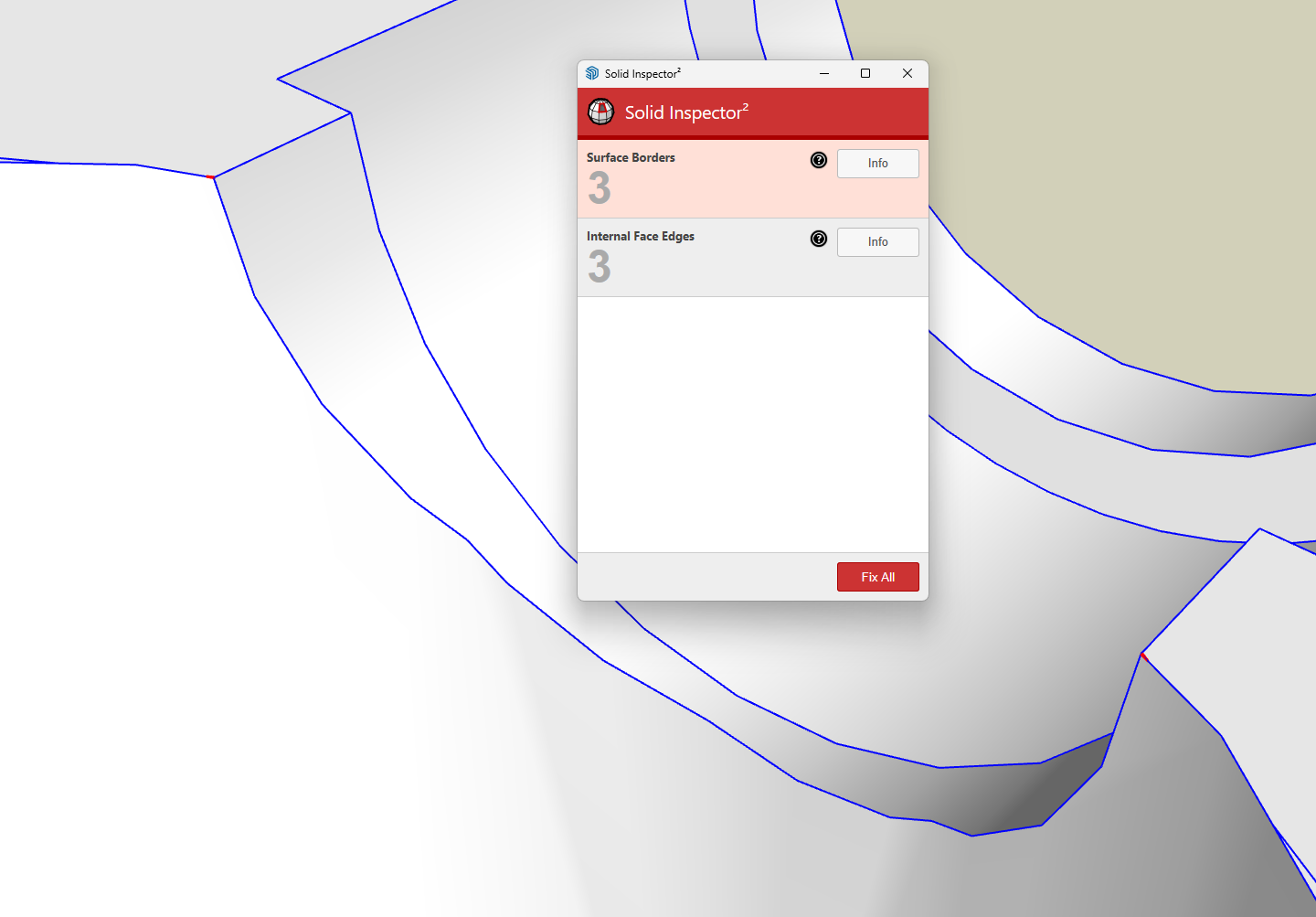
SOLID INSPECTOR 2 (which is really great) reports 3 surface borders and 3 internal face edges, but I cannot see any red whatsoever. I use x-ray, scaled up 10 times, close in inspection, but nada. Can't find any red.
I have 2 nearly identical models but both report the same problem.
I need a more experienced set of eyes or better tools to find them for me.
Please, do not fix it for me. Just show me where the problems are.
Swing Table - Lower - with problems.skp
Thanks, jgb -
Highlight one of the error lines and tap Tab to zoom in to the error. Tap again to go to the next one. Rinse and repeat.
BTW, you should clean up your model a bit. Looks like you had overlapping circles on that large central hole.
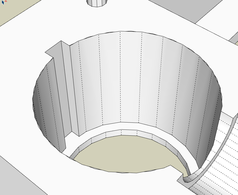
When I model for 3D printing I model as if millimeters are meters with Model Units set to Meters. I export the .stl file with Export Units set to Meters and open in the slicer as Millimeters. No tiny face issues which is the reason for the errors on the edge of that large hole.
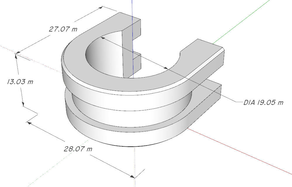
Example: This is the SketchUp model.
And the 3D print.
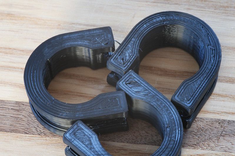
It snaps onto a 19mm diameter tube.Etaoin Shrdlu
%
(THERE'S NO PLACE LIKE)
G28 X0.0 Y0.0 Z0.0
M30
%
-
Poking around a little more I see you have set the back face color to match the front face color. That's a lousy workflow. It makes it more difficult for you to see holes (missing afaces) and it makes it impossible to detect incorrectly oriented faces. Face origintation is especially important for 3D printing because that tells the slicer which side of the face is the print media and which side is air. In your model you have a number of incorrectly oriented faces. Make the back face color significantly different from the front face color. If you have set the back face color to white for your template you should deal with it and create a new template.
Etaoin Shrdlu
%
(THERE'S NO PLACE LIKE)
G28 X0.0 Y0.0 Z0.0
M30
%
-
Thank you Dave. That helped a lot to clean up the parts.
However, not the problems I posted.
Solid Inspector never flagged those "overlapped circle" edges, and I never noticed them either. I was looking for red edges.
"Tab" doesn't work in SU 2015, but I'll keep tat in mind when I finally upgrade to SU-2025/26 and a 64 bit PC.
As for model scaling, I draw in centimetres, print in millimetres (10:1).
Any idea on the surface borders and internal face edges?
jgb
jgb
-
I normally make front/back faces the same, as colour differences show up along edges.
Solid Inspector correctly orients the faces. Yes, in some cases I will temporarily change color on one of a pair of faces to easily see interference's and holes, but when fixed, they go back to a solid colour.
But when I am in the throes of design I keep the part in default "no" colour both sides and if needed, just colour the component as a whole.
When I went back to the model, I cannot see any difference in front/back face colours. How did you see that? How can I fix that?
jgb
-
@jgb said in Model for 3D print will not make solid (SU 2015):
I normally make front/back faces the same, as colour differences show up along edges.
That's OK for output but it leads to sloppy modeling if that's your working style.
@jgb said in Model for 3D print will not make solid (SU 2015):
Solid Inspector correctly orients the faces.
Sometimes it does. Sometimes it doesn't.
@jgb said in Model for 3D print will not make solid (SU 2015):
When I went back to the model, I cannot see any difference in front/back face colours. How did you see that? How can I fix that?
I selected a style with the default blue back face color.
@jgb said in Model for 3D print will not make solid (SU 2015):
But when I am in the throes of design I keep the part in default "no" colour both sides and if needed, just colour the component as a whole.
Personally I prefer to keep the file neat as I go even when I'm in the "throes of design." It's generally quicker and easier to deal with exposed backfaces when and if they occur. With the right work flow you should rarely need to stop and fix face orientation anyway.
-
@jgb said in Model for 3D print will not make solid (SU 2015):
Solid Inspector never flagged those "overlapped circle" edges, and I never noticed them either.
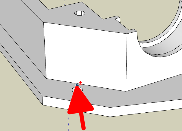
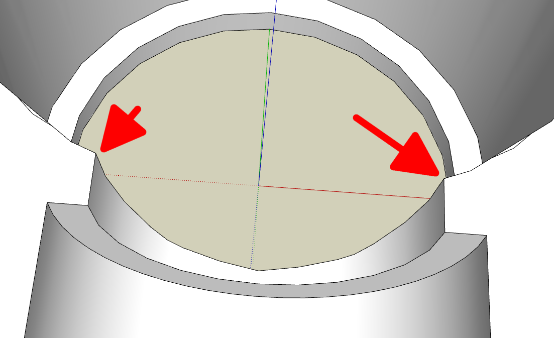
Except for the two missing faces at the corners where the horizontal opening is, the other edges were not preventing the object from being solid so no reason for Solid Inspector or Solid Inspector 2 to identify them. The reason I mentioned them is there's no reason for those edges to exist in the first place and they could later cause you problems.
@jgb said in Model for 3D print will not make solid (SU 2015):
"Tab" doesn't work in SU 2015,
It should. Are you using Solid Inspector2?
@jgb said in Model for 3D print will not make solid (SU 2015):
As for model scaling, I draw in centimetres, print in millimetres (10:1).
Do whatever you want. Had you been modeling in meters you likely wouldn't have had any of the surfaces borders (missing faces) to fix in the first place.
@jgb said in Model for 3D print will not make solid (SU 2015):
Any idea on the surface borders and internal face edges?
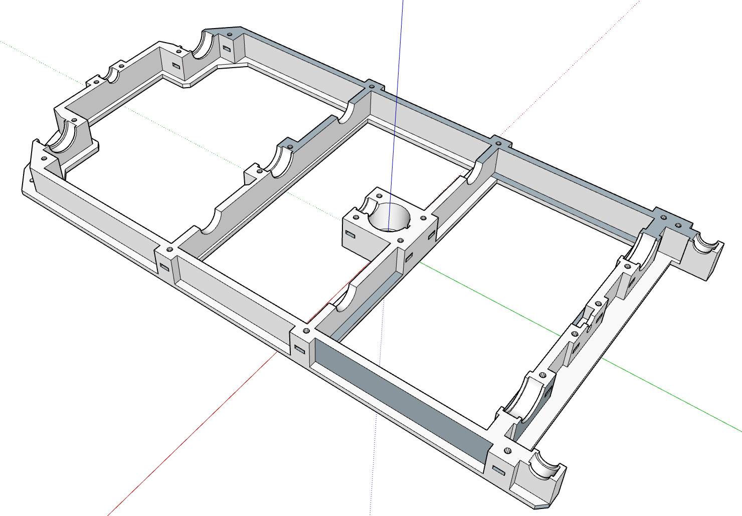
I showed you where they are.
Here, again.
-
Dave,
Thanks again. I never knew about using "tab" in Solid Inspector 2. And when I tried it on your first suggestion, I did it wrong.It took 2 minutes to solidify both components using tab in SI-2.
That would have saved me a lot of time and hair if I had known it before.
Now I can go back and solidify some other "non-solid" models.Next model I will try using meters instead of centimetres. Just that 10:1 is easier to work with than 100:1 as I have to visualize the model against a ruler to get some sizing correct.
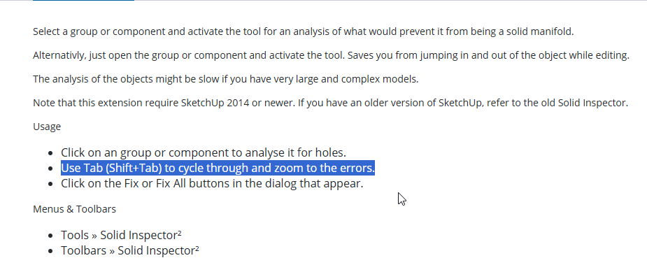
Alternatively, just open the group or component and activate the tool. Saves you from jumping in and out of the object while editing.
Doesn't work for me. What am I missing here?
jgb
-
You're welcome.
@jgb said in Model for 3D print will not make solid (SU 2015):
I never knew about using "tab" in Solid Inspector 2.
It's a good idea to check out the message line at the lower left of the model window whenver you start a tool.

@jgb said in Model for 3D print will not make solid (SU 2015):
Next model I will try using meters instead of centimetres. Just that 10:1 is easier to work with than 100:1 as I have to visualize the model against a ruler to get some sizing correct.
You misunderstand what I told you. There's no need to deal with 10:1 or 100:1 at all. Set the model units to meters. Read millimeters off your ruler and just enter them without doing any math at all. If you measure 15 millimeters on the ruler enter 15 in SketchUp. It'll go in as meters but you don't need to do anything with that. When you export the .stl export it with Model Units set to meters. When you open it in the slicer it'll be in millimeters and you don't have to do anything as far as the scale goes.
Here's another example. Model in SketchUp with units set to meters. The screws are M6 but the threaded part is modeled at a hair under 6 meters in diameter.
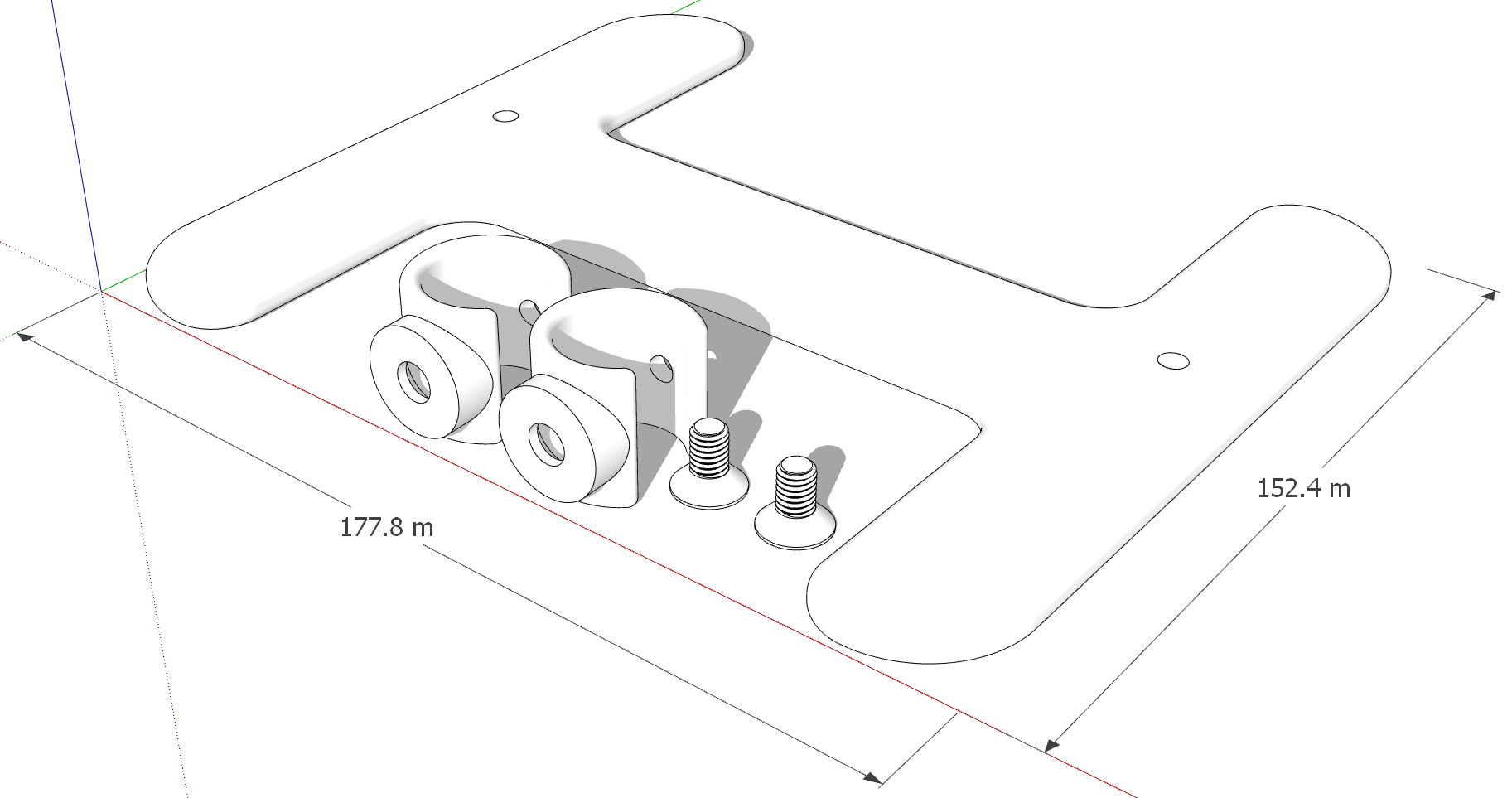
And the 3D printed parts.
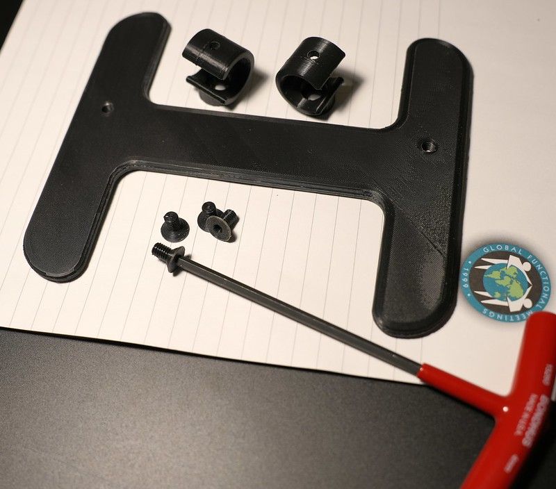
The M6 screws fit into the tapped M6 holes just like their commercially made metal counterparts would.
@jgb said in Model for 3D print will not make solid (SU 2015):
Alternatively, just open the group or component and activate the tool. Saves you from jumping in and out of the object while editing.
Doesn't work for me. What am I missing here?
I guess you'd have to ask Thom Thom about that one.
-
OK, I'll try meters next 3D printed model.
Again, thanks for the help and advice.jgb
Hello! It looks like you're interested in this conversation, but you don't have an account yet.
Getting fed up of having to scroll through the same posts each visit? When you register for an account, you'll always come back to exactly where you were before, and choose to be notified of new replies (either via email, or push notification). You'll also be able to save bookmarks and upvote posts to show your appreciation to other community members.
With your input, this post could be even better 💗
Register Login


Advertisement