Creating Dynamic Component Question - Cabinet Doors

-
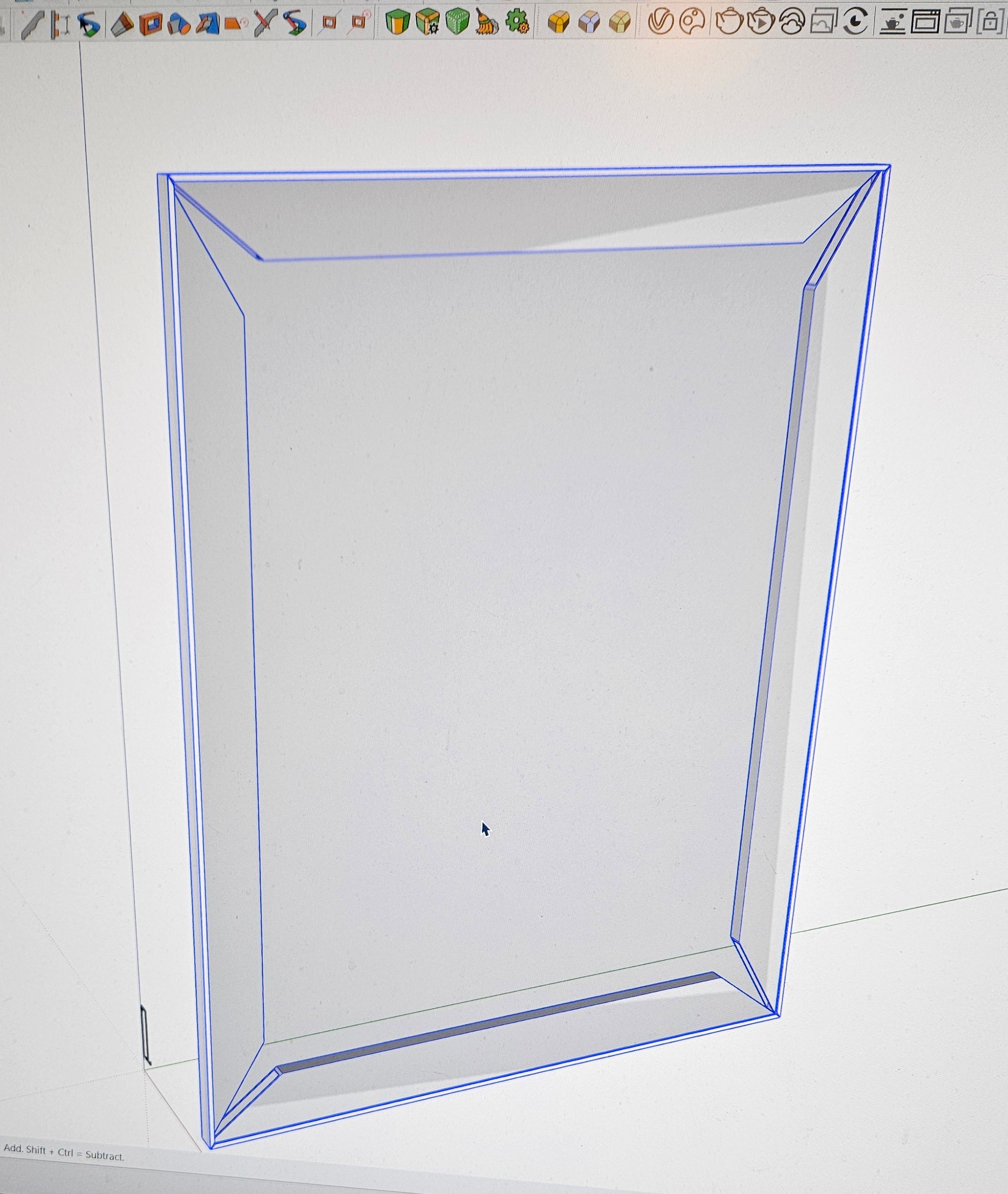
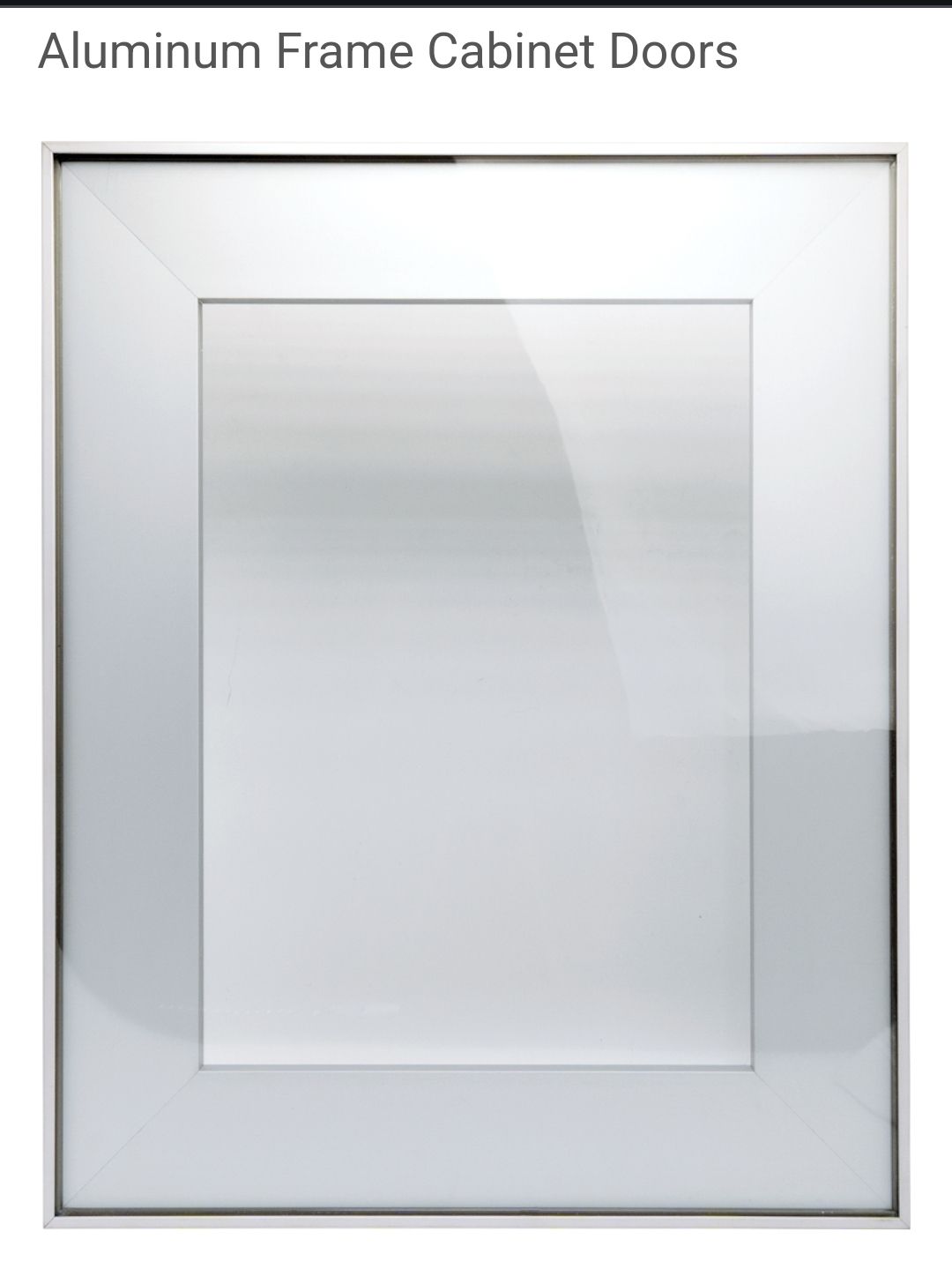
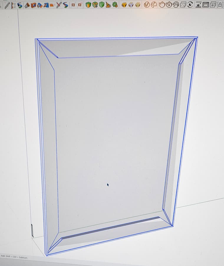
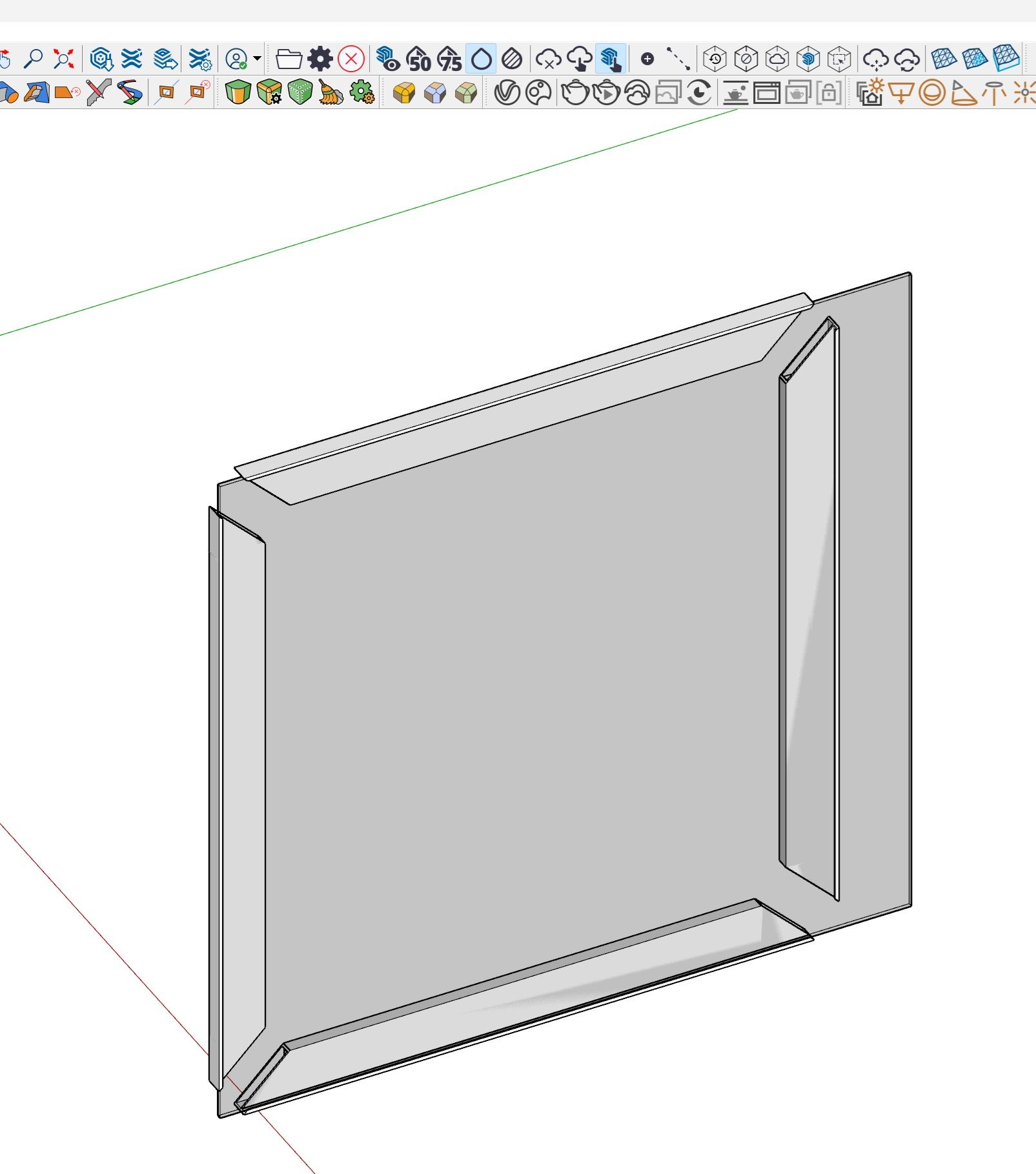
Hey, hoping I can find an answer or someone can direct me to a good tutorial. New to using dynamic component feature. I am trying to create a scalable component of this aluminum framed cabinet door. I want to be able to scale to a cabinet front size without losing the fixed dimensions of the profile. I created the stiles, rails and center panel, assigned fixed attributed to the X and Z lenses and left the Y lens adjustable on the stiles and rails. It looks good until I try to scale it and I end up with open miters.
Anybody have a fix for this or know where I can find a tutorial on how to do this correctly? Any help would be much appreciated!
-
@jcarterKBdesign As you found, changing the length of the components is scaling operation. If you think about the miters as triangles, you're scaling the triangle along one leg which changes the angle of the hypotenuse. Simple geometry.
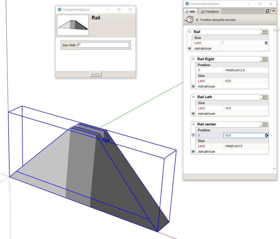
In the case of your mitered door frame you would need to split the rails and stiles into three separate components, a middle section with square ends and then a triangular component for the miter at each end. Then the setup for the DC would involve scaling the length of the center section and moving one of the end components. That will keep the 45° miter with length changes.
If you don't want to see the seam line between the three components, hide the end faces and their bounding edges to make the rail or stile look like a single object.
I did a quick example for one rail. I painted each component with a different shade of gray to show there are three separate ones.
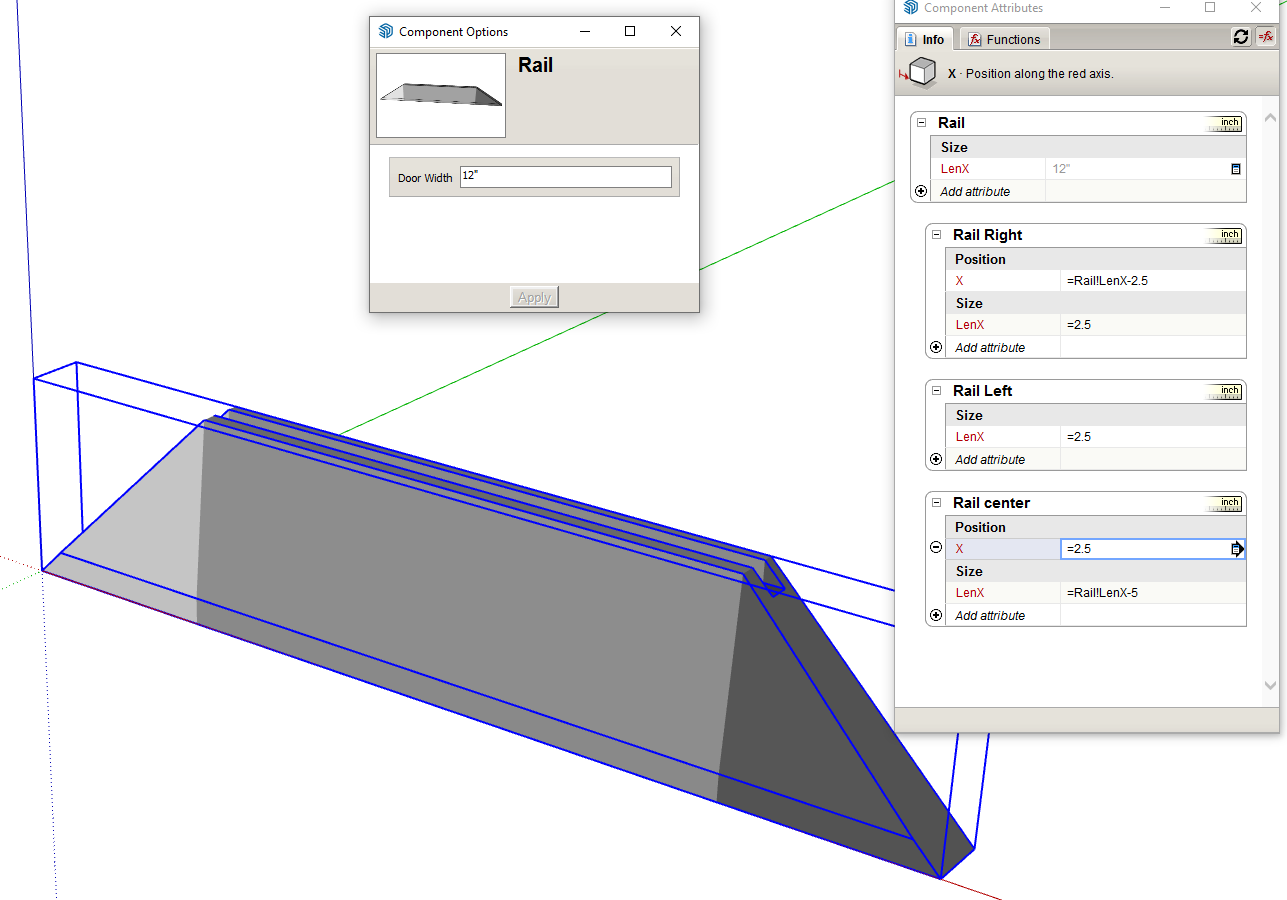
And with the overall length changed.
-
@Dave-R Wow! Thanks so much for the quick reply and detailed answer. When I get back home I will follow your instructions and report back with results!
-
@jcarterKBdesign you're quite welcome.
A couple of things I maybe should have mentioned:
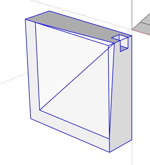
Building the model as I have here, the door frame would be made up of 12 components, 3 for each side of the frame. You could reduce that number to eight if you model the corners like this.
Not sure if it would be needed but if you were modeling a raised panel for the door, it would need to be divided into nine components. One for the center, one for each side, and one for each corner.
-
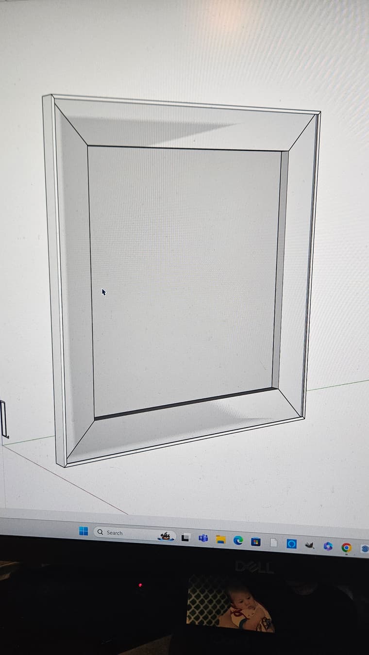
@Dave-R Back for some more free advice! So your method worked for the individual rails but when I go to scale the door as a whole I get this. Any advice on how to fix this issue? I know there is a Fredo tool for scaling components but at this point I'm determined to learn how to do this! !!
-
@jcarterKBdesign It would help to see your .skp file to see how you've set up the properties for positioning the components. Looks like you've got the position properties set up incorrectly.
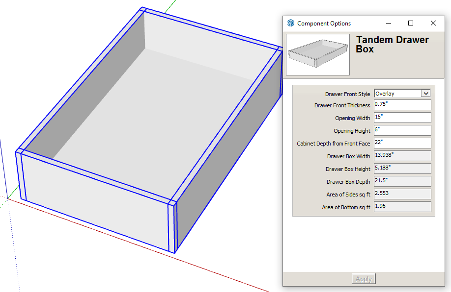
Personally I wouldn't use Scale. Instead I would set up fields so I can just type in the dimensions I want for the door. Here's an example DC that I created for a drawer box.

The first fields with the white backgrounds are for user entry. The ones with the gray backgrounds are information that can be included in a report so the manufacturer can quote the price and make the drawers in the project. -
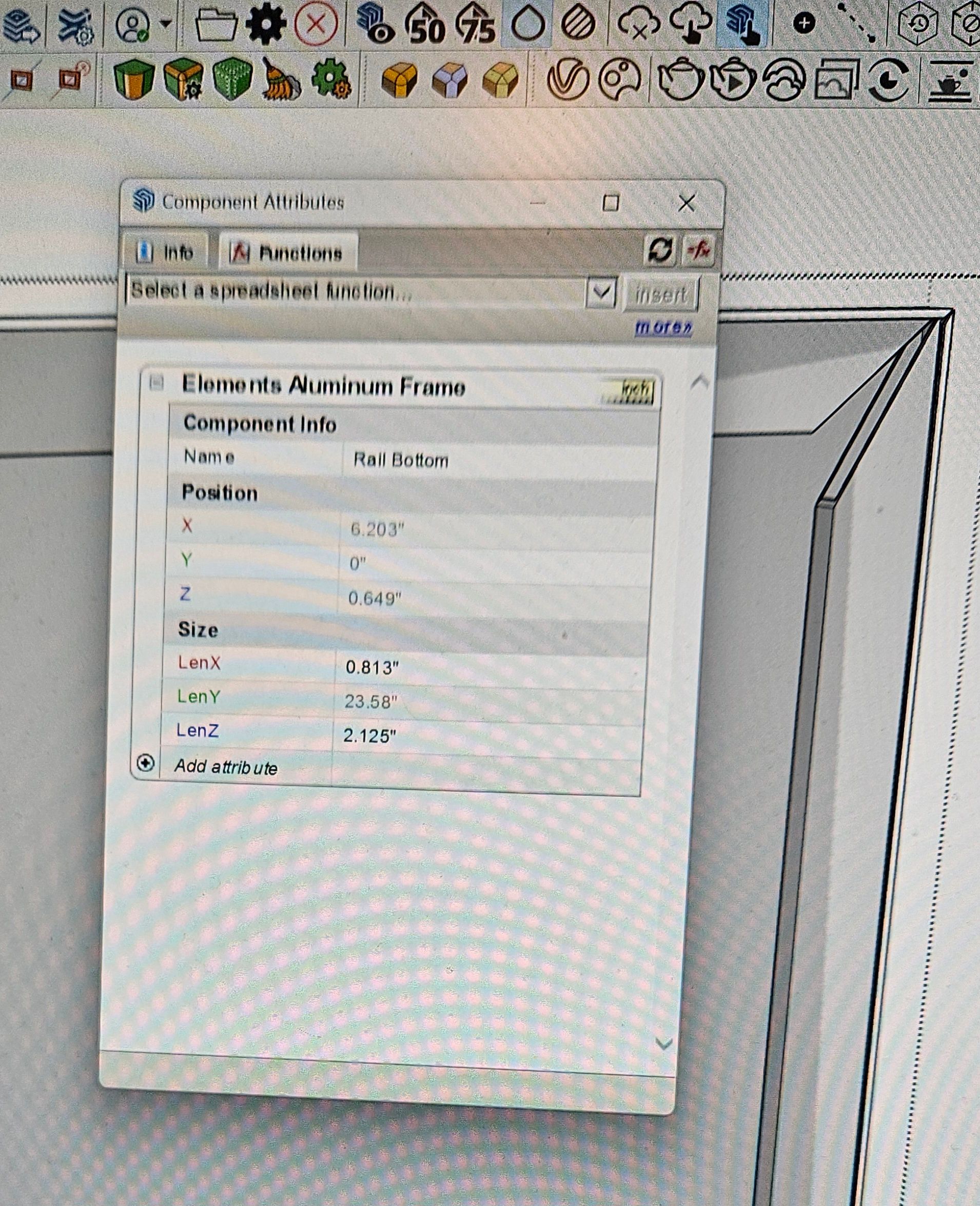
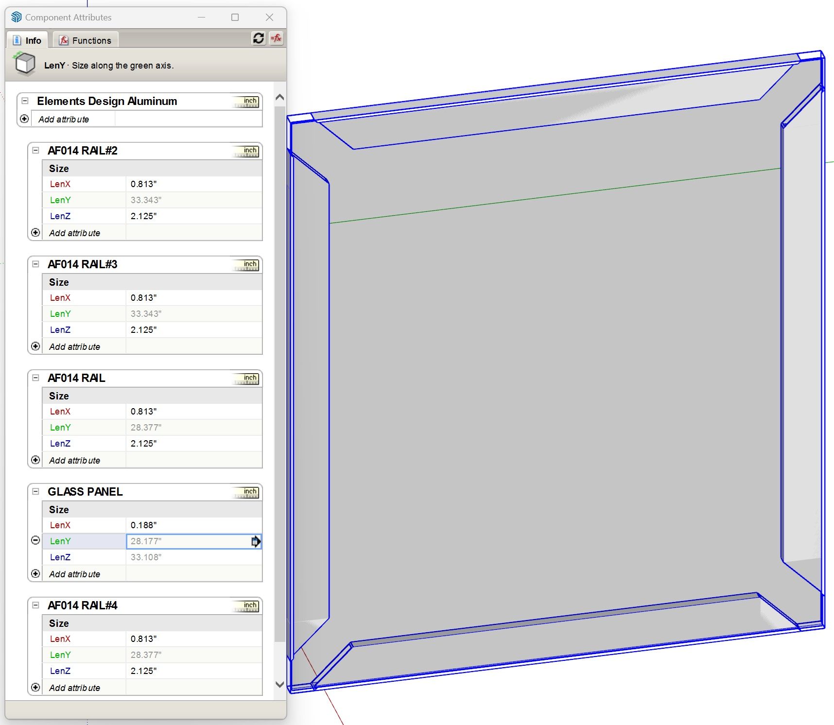
@Dave-R this is what I have. I didn't set any positions so that's probably what's messing me up.
-
@jcarterKBdesign The horizontal rails need to have their X Position locked to the left corners of the left hand stile. The X Position of the right hand stile needs to be based on the width of the door
Here in my drawer component you can see how the positions of some of the elements are established. In this case the drawer box component's axes are placed so the drawer can be dropped into place at the front lower left corner of the opening and leave the required spacing.
Hello! It looks like you're interested in this conversation, but you don't have an account yet.
Getting fed up of having to scroll through the same posts each visit? When you register for an account, you'll always come back to exactly where you were before, and choose to be notified of new replies (either via email, or push notification). You'll also be able to save bookmarks and upvote posts to show your appreciation to other community members.
With your input, this post could be even better 💗
Register Login


Advertisement