Tool Path Chamfer - Complex Curved Faces/ Edges - Help!
-
Hi all and thanks for your time : )
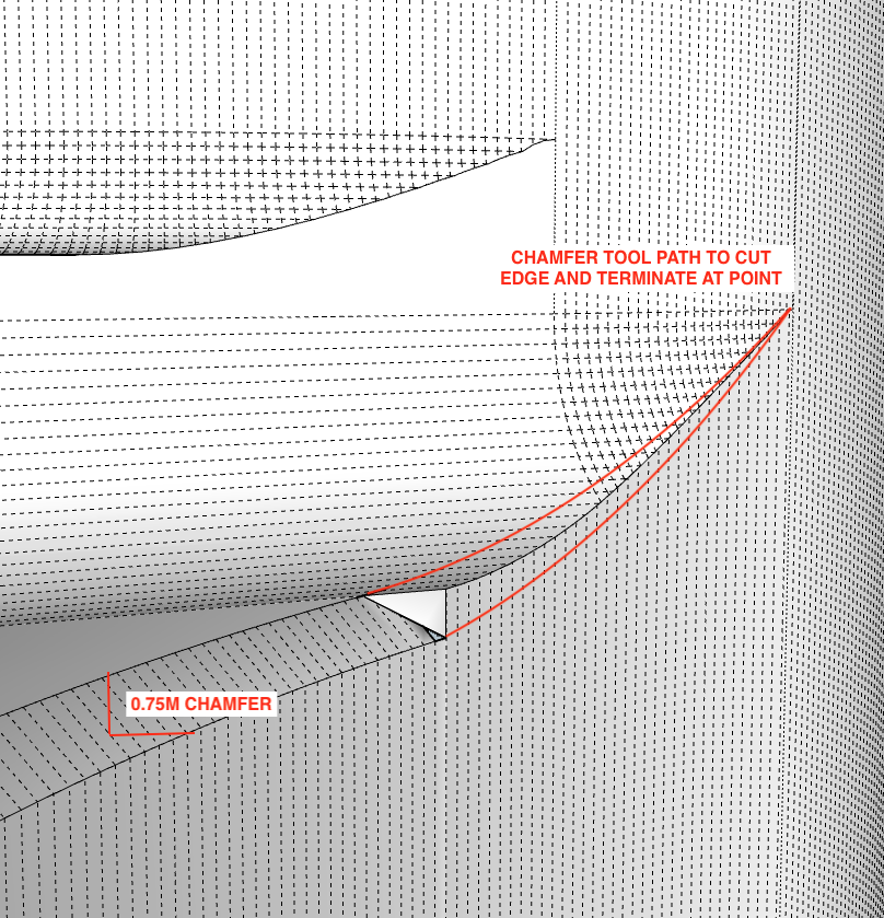
I'm working on a component for prototyping and ultimately CNC machining. I have a number of complex/variable curved faces and edges which require 0.75mm (0.75m in model) chamfers that terminate to a point. How do I model this tool path accurately?
To this point I have found some success with solid subtractions. Using the follow-me tool to match the edge contour and radial bending to mimic the tooling pull off. However, this is a sort of freestyle method and although it does the job visually it isn't passable for the finished product.
Here is the model if anyone would be so kind as to give it a go.
https://www.dropbox.com/scl/fi/d868sp7yoneeox5snosbh/Part.skp?rlkey=wno59nrswa1q6r1o17nr5u9hl&dl=0Any thoughts, feedback, and recommendations are greatly appreciated.
Thnx again

-
If you use Tools on Surface to draw the red lines then remove the unwanted material. You could then loft the surface either by hand or by extension.
But at 0.75mm I'd break out a hand file and give it a quick rub.
-
Thank you Rich!
Fantastic idea. This worked perfectly : )
I had another tip come in to try the extrude edges by vector to object tool. Transfer the edge to a surface, draw the chamfer curve and transfer back to the object. Loft the surface. A combination of this method as well as yours got me through this task.
I appreciate your guidance.
Thnx again
Advertisement


