2D Ain't All That
-
Not sure how that happened. I guess you got the other information from a section. Could be the draftsman, not having seen a finished product, was incorrectly inferring what happens when the fins hit a dome shape. I wonder if the machinist had to squint at that a moment before ignoring it.
I am still in awe of all the things designed and built with 2d projection drawings, especially in a building like an old theater with ornate arches and curves going in every direction.
I am tempted to fall in the rabbit hole of what these fins are for and why they are so shaped, and so put of getting to work. I wasn't aware of this complexity in train wheels.
And kudos for modeling skill! Looks cool!
-
Peter, I did get the other information from a section. The section had most of the dimensions on it.
I am often amazed that those folks in the old days could make up those drawings and have them accurate. In the case of this wheel, I expect it was cast and then had some forging and machining work done to it. I imagine those fins were to add some strength but they may have helped move some air to help keep the bearings cooler. Or that might have been the intention. Evidently that sort of construction didn't last very long. You don't see fins like that on wheels today nor even on wheels from 80 or 100 years ago.
I was more surprised by the hollow part around the hub.
-
Another cool model out of the past . Wonder if the issue with the fins might’ve been one of those cases of “ you just can’t quite get a perfect representation of somethings in a 2D plan “ They did have 3D models back in the day. They were called Pattern Makers . It was up to their skilled hands to work out what wasn’t always clear in the drawings.

-
Thank you, sir.
The pattern makers were artists, weren't they.
I was talking with my brother about this wheel last night and we started wondering if wheels like this were actually produced. Maybe they made one or two and decided there were too many quality control problems associated with casting them. The curved fins would be a challenge to cast correctly.
And your point about what is shown in the 2D drawings is good. I am certain there were times (and probably still are today) when it was enough to simplify the drawing.
Again, not a cool as some of the models in the Gallery since it's only one object but it was interesting for me to model and I learned some things. That's mostly all I care about anyway.
-
Don't know about others but I think your "blast from the past" models of early industrial age bits are just as cool as any space ship , car or what have you. So please keep them coming. Perhaps I didn't come across so well in my earlier post.. not sure "simplify" would be an apt description. My experience drafting many years ago made it pretty clear there where somethings that are just real difficult to be 100% accurate when preparing mechanical drawings . Compound curves in my memory were a pure bitch at times to get right. Recall reading years ago the early pattern makers had a lot of back and forth "conversations" with the draftsmen to get things right.
-
Thank you. It seems from the Gallery that most users seem to prefer photo-realistic renders of complex scenes but no matter. As long as you like these things that's enough for me.
I did get what you meant about the 2D drawings.Some things are hard to draw in 2D in a way that they can accurately convey what a 3D model can. Of course that back and forth between draftsperson and patternmaker or anyone manufacturing something should be there.
-
-
Ha! You didn't get me this time. No beer in my mouth.

-
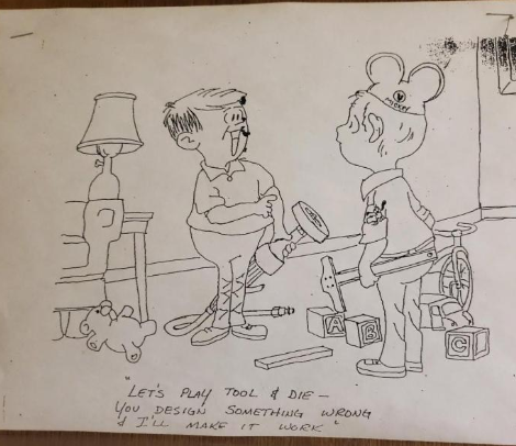
My brother just sent me this.


-
A few years ago I was asked by a client to model a set of plans for a very large maintenance facility at an oil refinery, just for presentation to the men in suits, you understand.
The model revealed that the gantry crane rails would collide with one of the huge roller doors.
When informed the architects called BS, they said SU was a toy. I had to go visit and show them on my laptop, they were not happy.
I probably saved them a hundred grand, it would have been a huge cockup.
Never got a thank you from them but the client insisted on models from me from then on. -
Baz, I had a similar experience related to the replacement of OR lights and the addition of some articulated equipment booms. The vendor showed a floor plan with circles drawn to show the area the equipment could cover but not the volume of space the equipment would consume in the room. As it turned out, the proposed placement of the equipment and where it mounted on the ceiling meant that it couldn't be used in the primary location. If the boom was positioned where they wanted it during use, they couldn't get the patient in the room. And it couldn't be place on the other side of the table to allow the patient to come in because they'd have to take the equipment over the patient once they were on the table and that is prohibited. The vendor wasn't happy because they had to go back and rework things and the project manager was at first upset because of the delay in the project and the need to schedule another meeting. She figured out though that it saved the hospital a pile of money, though.
Advertisement


