Medeek Engineering
-
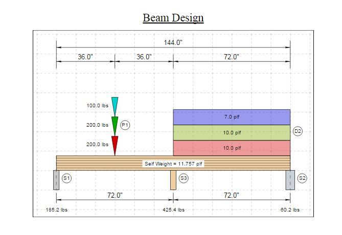
First look at a sample load diagram that will be generated within the report:
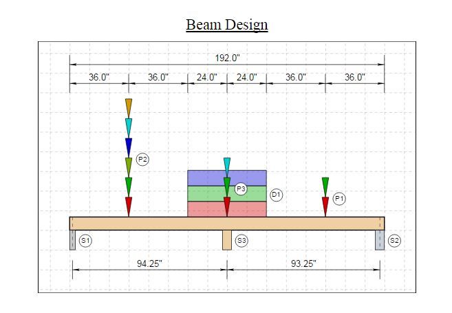
I was going to include the numerical values but it clutters things up too much so I think it makes more sense to just include the appropriate tables below the diagram with all of that information.
Notice how P3 is essentially on top of D1. The point loads and distributed loads can be anywhere along the beam so things may become a little cluttered even with my best attempts at trying to make the diagram as clear as possible.
If you look at the output from Weyerhaeuser's Forte app, my diagram is similar in many respects but somewhat more detailed.
One thing I have not considered yet is what if the user wants to input negative (uplift) loads. I will need to give that some more thought and figure out if that is something I should add and then determine how to best represent an uplift load.
The other thing I realized is that unlike a truss, I'm actually only dealing with a one dimensional structural entity here. Do I really need the grid? It does help show the size of the beam (the length and depth are to scale) but otherwise there is really no need for it.
Thoughts overall?
-
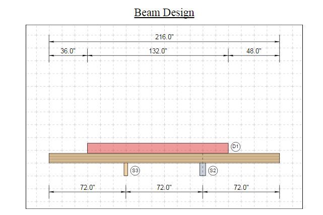
Now that I have the shear, moment, slope and deflections algorithms in place for point loads it is just a matter of algebraically adding multiple loads for more complex loading scenarios (ie. multiple loads and load cases). Here is a very simple example of two point loads applied to a two span beam. Note that self weight of the beam is not yet being considered:
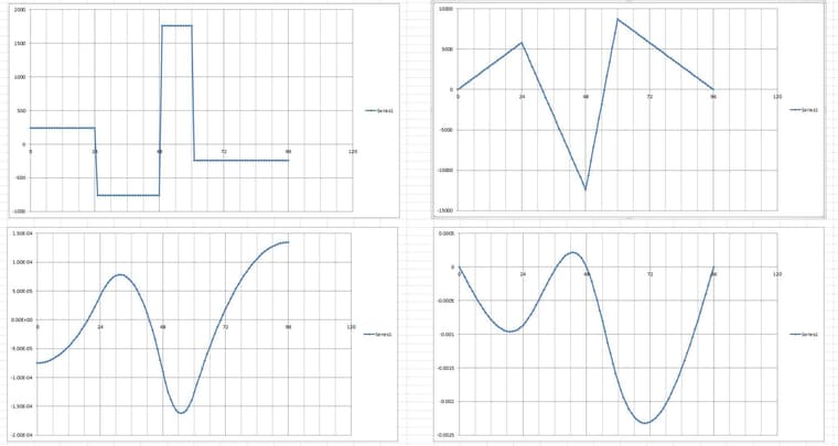
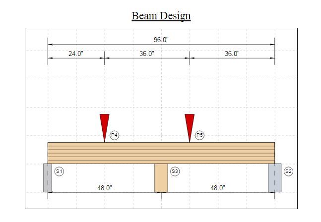
I need to add some formatting logic into the top beam diagram to account for shorter spans so the dimensions don’t run into the supports as shown. This is why a lot of testing and debugging is necessary.
This beam engineering tool with its matrix analysis engine is probably the single most complicated piece of code I’ve ever written, it certainly rivals the truss calculator (2013) and the complex roof (2019) module. I will admit that I now freely use ChatGPT with some of my coding puzzles lately and surprisingly it even understands the context of what I’m coding and offers suggestions to improve the accuracy and efficiency of the engine itself.
The numerical integration (for the slope and deflection) was initially stymied by incorrect boundary condition constants and I had no easy way of analytically solving for them. At that point I was fully aware of the issue but I was stumped at how to arrive at the right solution. ChatGPT suggested a normalization algorithm which proved to be correct and was even an easy fix within the algorithm. It’s like having a really smart graduate student looking over your shoulder pointing out what your doing wrong and how to make it all better.
-
I’ve been wanting to finish this beam calculator for some time now so I’m trying to dig deep and see if I can’t get it out the door, even if it only has the capabilities to handle wood (sawn lumber, glulam, SCL, I-Joist) beams and joists initially..
Unlike my previous web based beam calculator this new tool will be completely open ended, there will be no limit on the number of supports or loads one can assign. Each load can have up to six different load types (dead, live, live roof, snow, wind, or seismic) So in a sense it is a general solver or engine which makes it quite powerful and much more useful in my opinion.
The one other harsh reality with engineering though is that the code is always changing. I will need to continually update the tool as future revisions to the ASCE7 and NDS are released as applicable. I’ve noticed as I review various copies of the ASCE7 (2005 - 2022) that the load cases are continually changing, which I find a bit odd, you would think that after years of refining the code we would slowly arrive at suitable load combinations and stick with them. This constant flux is rather annoying to be perfectly honest, and makes me really question the powers that be and why they can’t iteratively arrive at a standard and eventually stick with it.
We all know how the (engineering) sausage is made. Why continually tweak the recipe? The technology and materials used in the building industry has not dramatically changed in my lifetime (50+ years). All of this continual tweaking and minor adjustments to the engineering code really does nothing to safety of the structure in my mind and simply adds to the cost of engineering since new software updates are required and additional training is imposed. Maybe the ASCE needs to keep itself relevant and the revenue from selling updated pricey copies of its signature standard (ASCE7) is a serious cash cow? I don’t know what the story is with all of this but I feel I need to rant a bit when I just shelled out $260.00 for a paperback book that I will only crack open once every few months at best.
Nathaniel P. Wilkerson PE
Medeek Engineering Inc
design.medeek.com -
@medeek said in Medeek Engineering:
you would think that after years of refining the code we would slowly arrive at suitable load combinations and stick with them.
yeah, but then without so many conflicting standards, where would we be? all those jobless standards bearers would be out on the street making mischief... lol
-
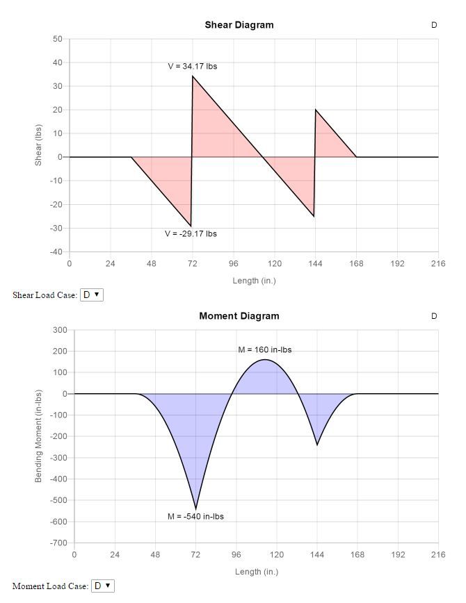
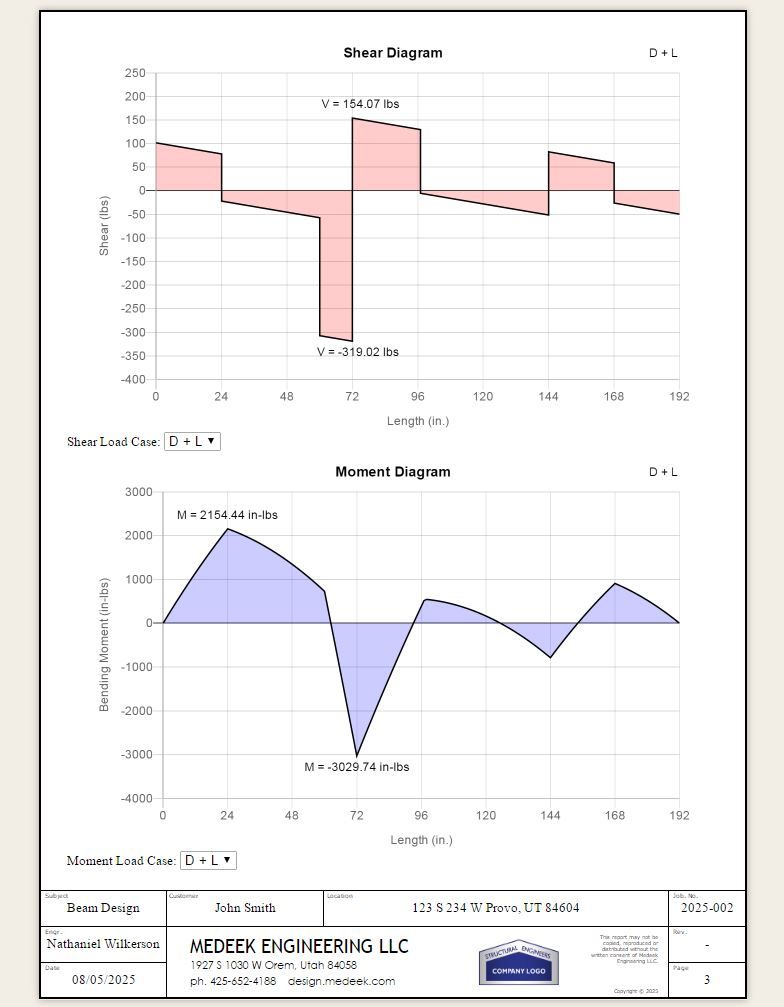
First look at the shear and moment diagrams being generated by the report generator. It took me most of yesterday and today to learn the ropes of Chart.js, an open source charting library for Javascript. It's not perfect but it does seem to get the job done. My only real issues with it is that I still can't figure out how to make it render to a higher resolution (300 dpi for printing purposes). The sample below is a screenshot of the PDF that is printed from the HTML output.

-
I am using the stiffness method per Ch. 15 of R.C. Hibbeler’s book, Structural Analysis. For intermediate loads between supports I use (FEM) fixed end moments. I’m actually still working on the matrix analysis piece. I’ve got point loads pretty much in place I’ve just got to implement distributed loads next. I suppose I could have it generate the entire polynomial for both shear and the moments since I am generating them for each applied load, it is probably just matter of using superposition on them as well.
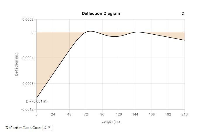
Here is a first look at the ability to switch between various load cases for the deflection graph:
-
Overhanging beams with point loads now check out. Once again ChatGPT to the rescue to help debug my syntax and even debug my actual algorithms. This AI stuff is getting crazy good, sometimes it makes mistakes but then it is able to reason and catch itself, it's uncanny.
Now I just need to debug for uniform distributed loads on overhanging beams. Then it is on to the actual engineering portion (AWC stuff for wood) and some final formatting of the PDF/HTML report.
I'm also not entirely satisfied with the clunkiness of the tools used to move and create the supports, some improvements on this end are needed. A load/support copy tool would be really nice, rather than having to create completely new loads and supports from scratch.
-
First look at partial UDLs with overhangs:
So with that I think the basic nuts and bolts of the matrix analysis engine is in place and functioning pretty much as expected. Of course it will probably be a few more days or even weeks before I am able to put out every little fire that may be burning undetected thus far, but we will see.
Now I will turn my attention to the following items on the todo list:
1.) Try to fix the truncation in the shear graph so that vertical jumps actually are vertical.
2.) Add in the standard engineering checks for wood beams (glulam, lumber, timber, LVL, SCL and PSL)
3.) Finish the formatting and layout of the HTML report. I may also include an option between a condensed report and a detailed report (or that may come later).Things that are not specifically on the todo list but are interesting:
- Add in fixed and partially fixed supports, currently every support is assumed pinned.
- Engineering for steel beams
- Trapezoidal distributed loads
- Moment loads
-
Version 0.8.1 - 09.07.2025
- Developed the matrix analysis engine for the beam calculator using the stiffness method.
- Added a load diagram to the beam report.
- Added shear and moment graph to the beam report.
- Added a deflection graph to the beam report.
The engineering report is still not complete however by rolling this beta release I can allow potential users of this plugin the ability to test it out and assist in the debugging. The plugin can be directly downloaded from this link:
-
Version 0.8.2 - 09.09.2025
- Enabled loads and reactions (values) within the load diagram.
- Fixed a bug with end supports that are not centered on the start or end of the beam.
- Improved the formatting logic (SVG and HTML) for the load diagram.
-
Working on assembling the actual engineering part of the report now, adjustment factors, shear, moments, deflection and bearing checks.
-
First look at the bearing check:
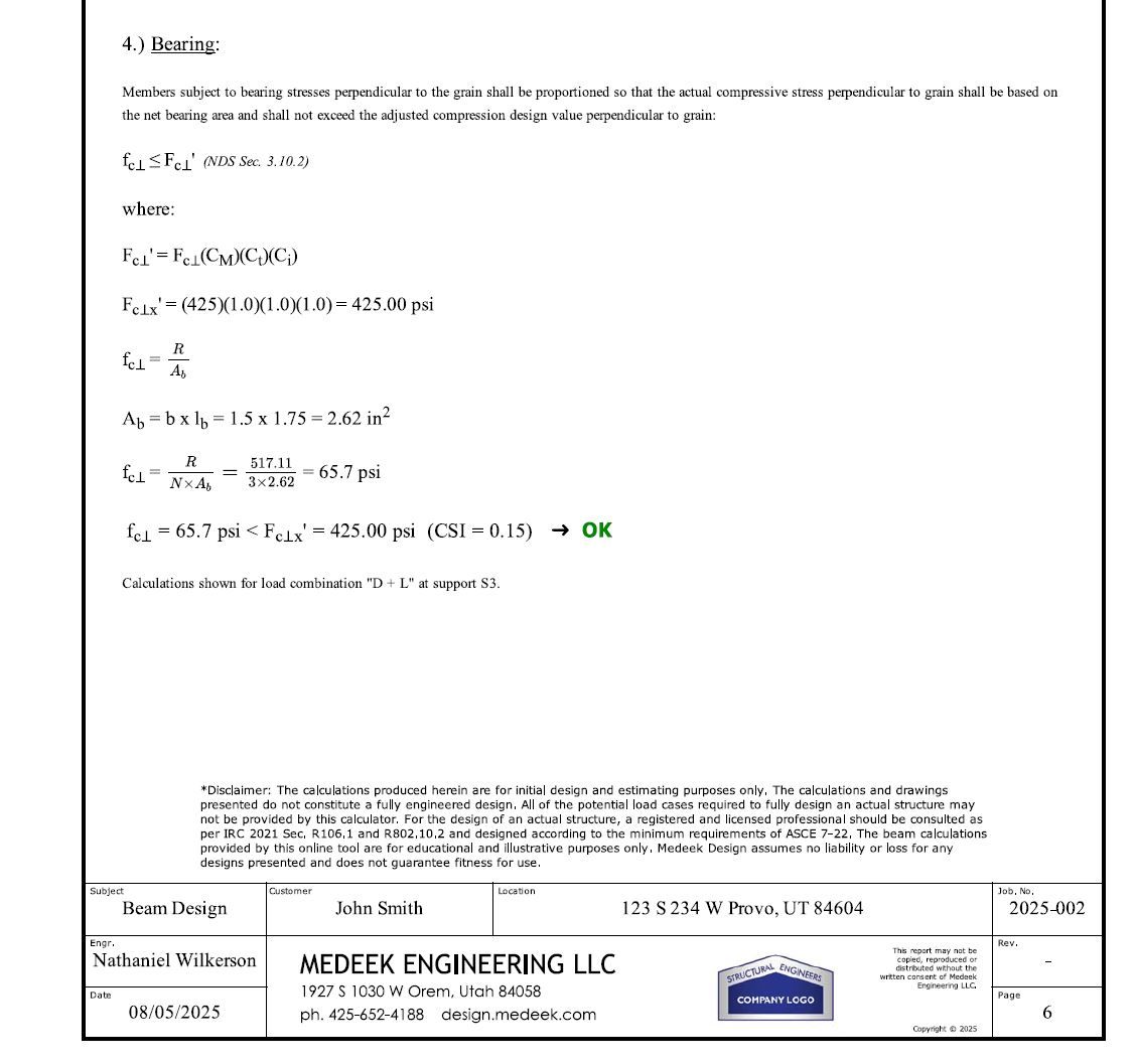
I also need to update my disclaimer, the disclaimer shown is for my previous online calculator, it needs some changes.
-
yeah i think keeping the disclaimer a bit more succinct - the first sentence, skip the next two, and keep the rest plus you might include the user assumes all liability for the use of this report blah blah blah.
-
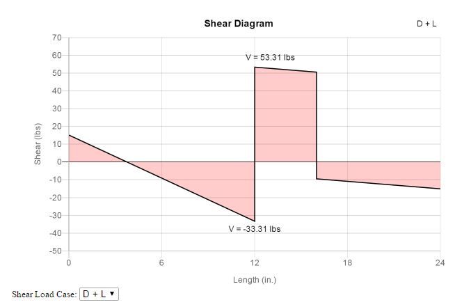
Spent the last two days adding in some additional code so that the vertical jumps in the shear graph (at point loads and supports) are actually vertical. It was a bit more complicated than I originally bargained on but I think I finally have it figured out:
The code seems fairly robust but tomorrow I will throw the kitchen sink at it to see if I can find any weaknesses in the algorithm.
I have't been posting much lately but that is because I've had my head buried in the code. Most of this engineering code is completely new (not my typical plugin stuff) so there is no refactoring old code or any other shortcuts I can take. Some of the old beam calculator is relevant however since it was so limited in its application I'm kind of on my own with this new calculator.
-
The vertical jumps now look at lot better. So far it seems pretty solid:
-
Here are the different EB (Euler-Bernoulli) and TIMO (Timoshenko) deflections for the same simple supported beam with a basic UDL (no self weight, just the external load applied) :
My parameters are:
2×10, L=144 in, E=1.7e6 psi, I=98.931 in⁴, A=13.875 in², G=106250 psi, κ=5/6
As you can see the Timoshenko analysis yields slightly more deflection since we are accounting for deflection from both shear and bending. According to my calculations my results are within less than 0.05% of the theoretical value so I think the algorithm is working correctly
Now I need to check a few different multi-span configurations as well as overhangs to make sure everything is indeed robust.
When I calculate the Timoshenko beam I'm wondering if I should adjust the tabulated E value since it is being adjusted for the shear already by %3 for sawn lumber per Appendix F of the NDS (Sec. F.3). So the listed value is is actually 3% larger than the (shear-free) or true value of E.
-
would an easy way to compare E with and without the adjustment in case it's significant enough for someone to review their parameters? e.g. https://woodengineering.com/2022/07/16/shear-free-eeee/
Glenn
-
I still have completely finished the PDF reports since I've had my head so buried in the Timoshenko stuff for a couple of weeks (probably not a good use of my time but I couldn't resist). Here is some output for a couple of cases (two span and three span beam, equal spans with a UDL). What is interesting is the shape of the deflection graphs for the Timoshenko analysis. I think the numbers are correct but to be honest I really don't have another 3rd party program I can fully test against.
I'm using a kappa of 5/6 and a G of 1/16 the E value, so in this case G = 106,250
Also I am just using the listed value of E for my Timoshenko calculations even though it already includes a 3% bump for shear built in.
EB = Euler Bernoulli, TIMO = Timoshenko
As a sanity check I multiplied my calculated value of G above by 10,000 in the code and then ran the TIMO analysis, the results are almost identical to the EB analysis as expected, so that tells me that with an extreme stiffness the TIMO degrades to an EB analysis as it should in theory. Here are the links to the TIMO analsys with a 10,000X inflated G:
-
Here are a couple examples, everything should be complete, but I will now spend the next couple of weeks error checking and seeing if I can break the engine or the report formatting. I will also need to test against other third party programs to make sure all my calcs are indeed correct. It is amazing how easy it is to make errors in the code on something this extensive.
https://design.medeek.com/resources/engplugin/TEST1/EB_TEST1_2SPAN_1POINT_REV8.pdf
https://design.medeek.com/resources/engplugin/TEST1/EB_TEST1_3SPAN_3POINT_REV1.pdf
Currently the calculator will only handle sawn lumber beams. Once I'm fairly certain I've eliminated any bugs or other issues I will then extend the logic so we can handle glulam and timber beams. Once that is done I will probably next work on LVL, LSL, and PSL and then finally I will include the ability to analyze various I-joists from the major manufacturers.
I've been slowly working on this for about three months now, probably another month to go.
-
Version 0.8.3 - 11.12.2025
- Enabled a detailed and simple engineering report/analysis for sawn lumber beams.
- Added an option to switch between Euler-Bernoulli and Timoshenko beam analysis.
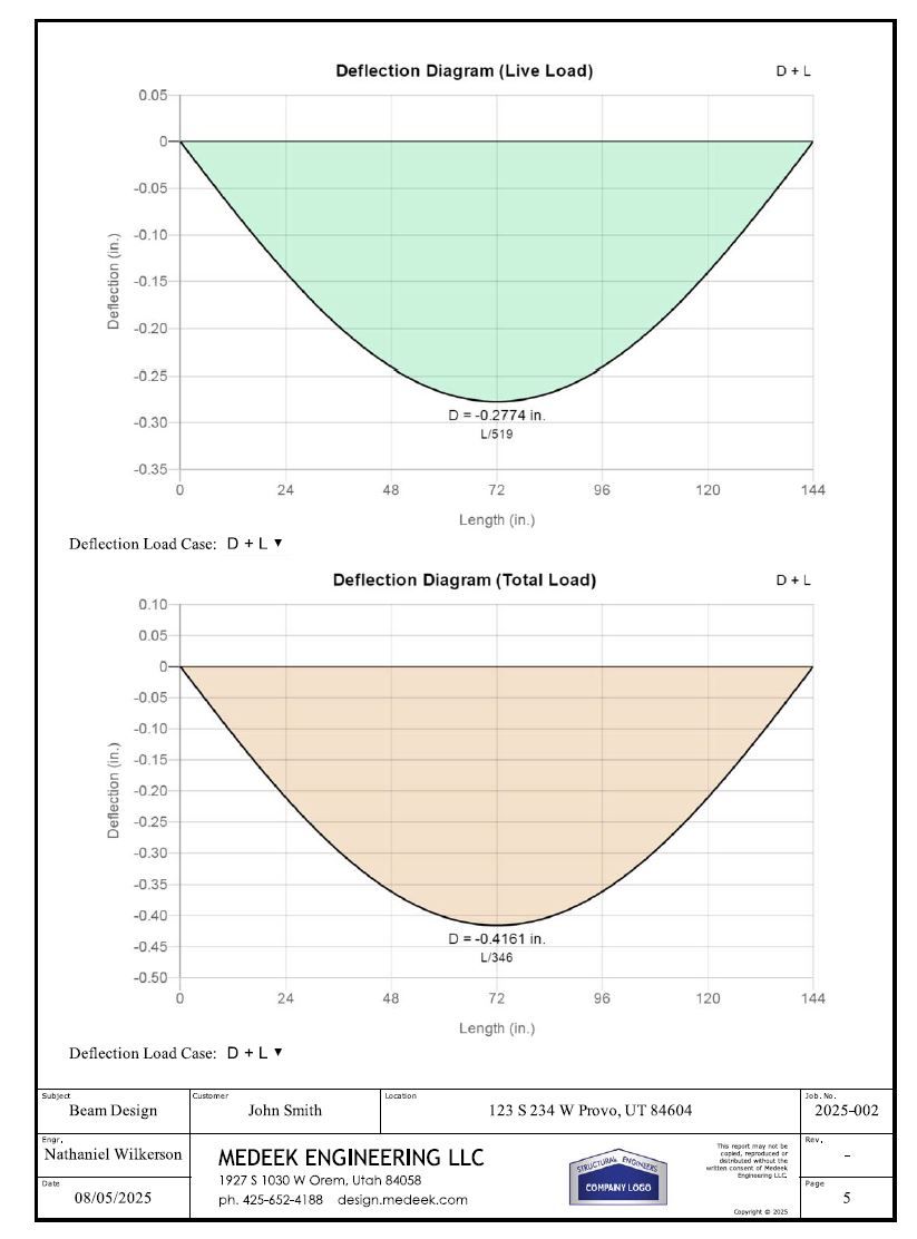
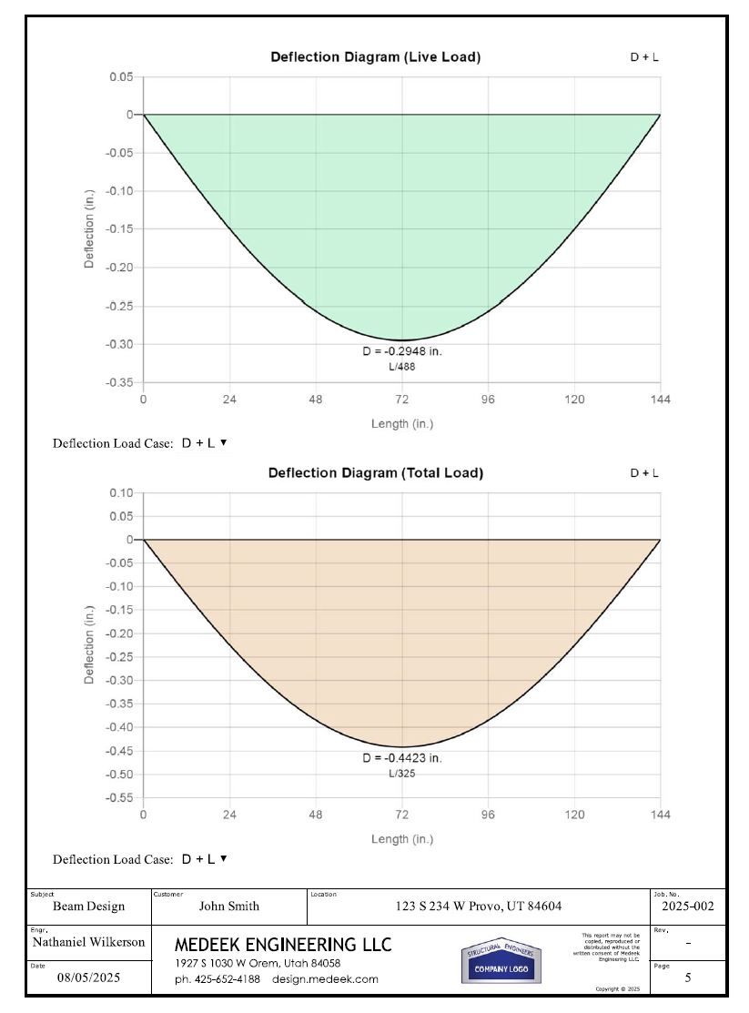
- Report now includes live load and total load deflection graphs.
- Shear, Moment and Deflection graphs can be toggled to all load combinations within the report.
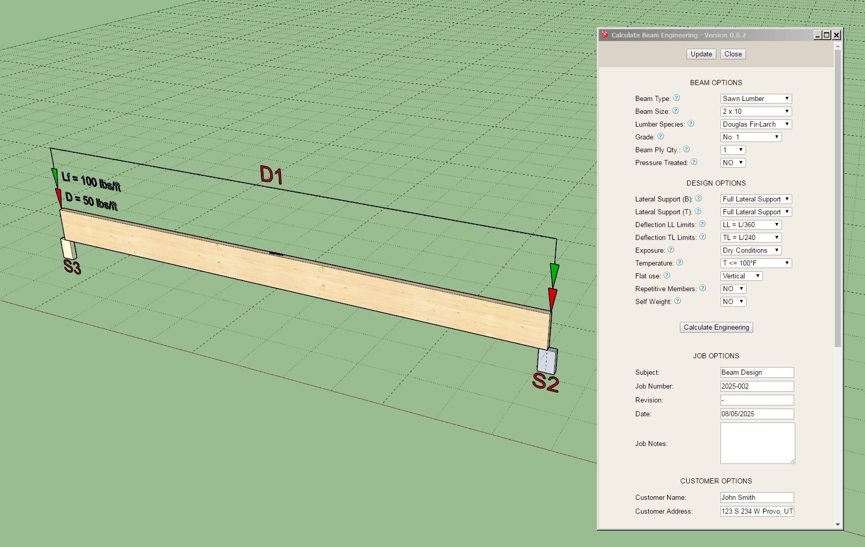
Tutorial 1 - Beam Calculator
I'm very excited about this release, it is the first time in history (that I know of) that one can do actual engineering all within SketchUp. The API is magical, you can turn SketchUp into just about any thing you can imagine.

Hello! It looks like you're interested in this conversation, but you don't have an account yet.
Getting fed up of having to scroll through the same posts each visit? When you register for an account, you'll always come back to exactly where you were before, and choose to be notified of new replies (either via email, or push notification). You'll also be able to save bookmarks and upvote posts to show your appreciation to other community members.
With your input, this post could be even better 💗
Register Login


Advertisement