Toposhaper
-
Arrived at sketchup, looking for an elegant solution to a seldom performed task:
Taking site levels, on a building exhibiting movement and generating a contour plot (on the basis that it's easier to look at a picture of the problem).
Now the old fashioned way has been to reduce the levels, plot on a drawing and draw lines of best fit with a pencil. subsequent to failing to be able to perform the elegant solution, that is what I did..
So retrospectively, because I am incredulous that I couldn't get this over the line, am looking to see if anyone can shed some light on the gaggle of issues that presented themselves.
The briefest of backgrounds:
- Looked for a way forward in CAD (ZWCad 2015), could generate points in space, but failed to create a surface... okay
- Found my way to the Toposhaper plugin, seemed like a solution.
- Downloaded Sketchup 2018, LibFredo and Toposhaper plugins and installed..
Now, importing the cloud of points from CAD, selecting the area contains them and selecting the contour from points cloud icon reveals the teeniest of tiny toolbars....(?) comparatively much smaller than the Sketchup toolbars, but can be read.
It all becomes a bit vague from that point, as shortly after this the program crashes, again and again and again, you get the picture.. Lots of "bugsplat" dialog boxes, until you give up.
Looking back at the net, I found another way forward, from a Sketchup tutorial (https://www.youtube.com/watch?v=oWjVrL0oetQ) that uses "Fredo tools" to draw the points over an imported image of a site plan.
I went back out there and download Fredo Tools, installed these, exited the program, start the program, no Fredo tools to be found.... checking the extension manager they are definitely there...That's when I went back to the pencil..
Days later I have returned to Sketchup and now see a new icon in the corner of the screen, I pick it up and move it. a few "tool" icons appear, I do it again and again, five layers down and at the bottom I find the "Fredo Tools" icon.....
Who would have thunk...........I return to the aforementioned tutorial and follow the directions, to create a cloud of points (with a similar teeny weeny toolbar....).
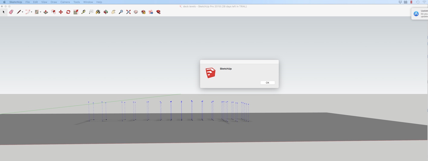
Upon selecting the points cloud and clicking the appropriate Topo icon, the program finds another way to fall over...
That has no real explanation, a dialog box with a Sketchup logo presents itself, with an "OK" button and nothing else...I have attached a screen shot..
This all seems to be a lot harder than it ever should have been....
Stu..
-
Could be your screen resolution. There is an issue with the toolbars and Retina displays. HOWEVER I also use Mac and for me it seems Fredo resolved that issue. I can't check right now, but I think the toolbars are OK for Toposhaper. My experience has been good, using imported contours. I haven't tried points.
I don't see a picture but this could be because you are new member. May take a few posts before you can upload files.
-
It would be useful that you post your model, screenshots of icons and anything that could help to understand your problem.
Fredo
-
Sure..
I do indeed have a Retina display....
Here (i hope) is the second file I worked on, the first was modified out of existence....
sketch file - based on youtube tutorial
A bit sketchy on the attachment process in here.... a bit convoluted and if the above worked at all, it is perhaps only one attachment per post.....?
-
Here is the first screenshot again, showing some sort of error....
Certainly, after clicking "OK" nothing is processed...
and this will be a screenshot demonstrating the difference in size, between the Sketchup toolbars and the plugin toolbars...
Hopefully these are legible, initially it seemed to be a file size issue, I had to shrink these a long way to get them to stick.....
thanks for your time..
-
Here are a few remarks
-
TopoShaper::PointCloud works on a group containing the guide points. So you have to put the UPPER guide points in a group.
-
Then you can easily generate the terrain
Regarding the small size of the button palette, this is strange because it should scale to your high-resolution screen.
Could you do 2 things
-
Open the Ruby console and type
UI.scale_factor. This returns the scale factor of your screen -
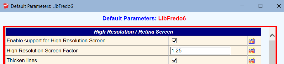
Go to Window > LibFredo6 Settings... > Default Parameters... At the top of the dialog box, you should have 3 lines like the ones below. Could you advise what you see (screenshot or value of the fields)
Thanks
Fredo
-
-
Thanks, it's encouraging to see it working on my points, I have attached a vid of what occurs my end...
So I guess this is a peculiarity of Sketchup....
I will attempt a reinstall, although this is the trial version, so unsure as to whether that is even possible....
I will also see if I can run these plugins with my Google sketchup8...
I do also have the info you requested:
My scale factor is 2
and a screen shot of the defaults -
thanks again..
-
-
I said that you have to enclose the guide points in a GROUP. And then operate TopoShaper on that group.
-
I don't know which version you have, but enter a value of 2 in the field 'High Resolution Screen Factor". This should make the button palette bigger.
-
-
and there it is....
EDIT/MAKE GROUP....
I went back in to the youtube tutorial and still didn't see that occur, it just, was....
The scaling factor worked a treat on the toolbar.
I found that I couldn't use the plugins with sketchup 8 and import dwg files for that matter, which is how I came to be looking at the current trial version at all.
Can you tell me, in the created topography, is it possible to delete the internal corner where there wasn't any data...?
-
@studoc64 said:
I found that I couldn't use the plugins with sketchup 8 and import dwg files for that matter, which is how I came to be looking at the current trial version at all.
In principle, TopoShaper and LibFredo6 works in Sketchup 8. Simply, you have no scaling of the text in the button palette.
@studoc64 said:
Can you tell me, in the created topography, is it possible to delete the internal corner where there wasn't any data...?
I am not sure I understand. You can define the boundaries for the terrain
- either using the options (best-fit rectangle, convex hull, concave hull]
- or by including a Face in the group where you have the guide point. The face will be used for defining the contour of the terrain.
-
Sure.. I guess mine is a fairly particular application of the plugin.
Generally I expect interpolation between and extrapolation of the available points to create a terrain is going to give the user something to work with.
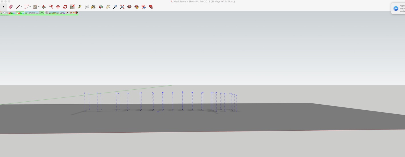
With my case of evaluating a floor plate, the floor actually stops along a given line...
see screenshot:
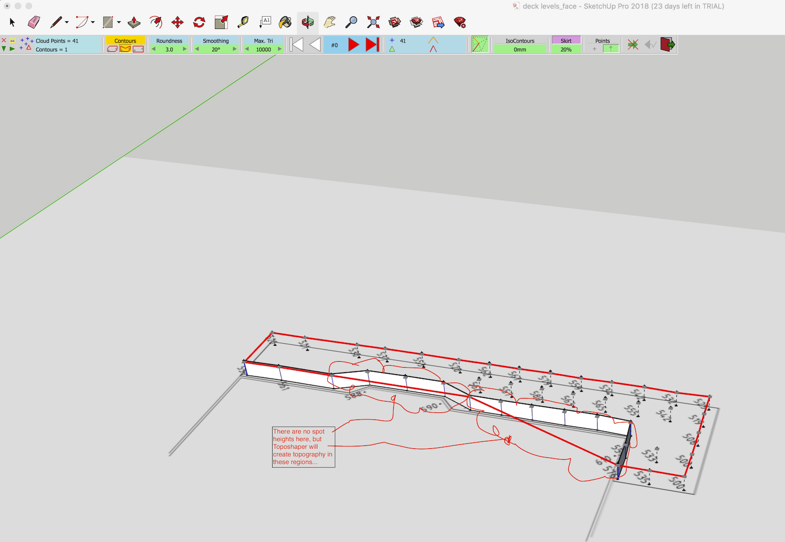
This is obviously a very powerful program and I am simply endeavouring to arrive at an outcome for my very particular condition.
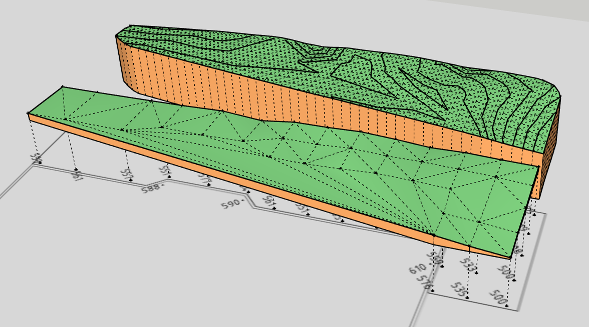
You can see above, I simplistically created a face at the boundary of the levels (where in fact a higher floor plate will commence), but the topography ultimately barges through this...
-
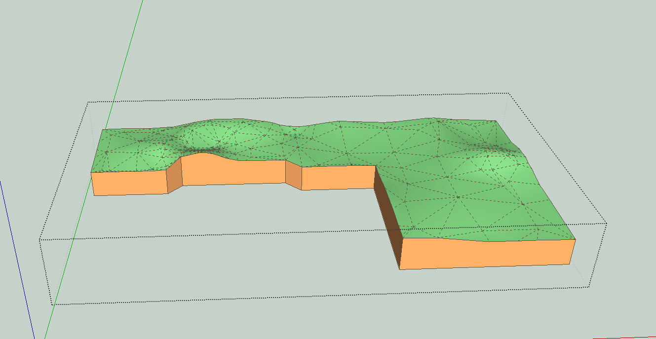
If you provide a face that is the perimeter that you want the terrain to cover, you get a display like this ( I drew a face below that Toposhaper is outlining in red). Include the face inside the group of points. See the first box now visible on the left of the control bar.
Then you get a terrain corresponding to the area of the face.
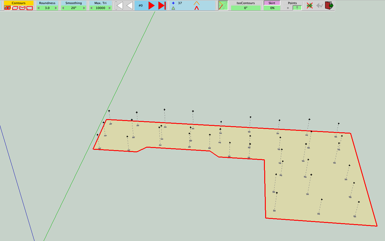
I made my own example because I use an older version of SU and could not use yours.
-
Oh... that is splendid....!
I can see that this could be useful to me...
I have managed to do the same..
Can I ask, is it possible have the contours labelled....?
vis.
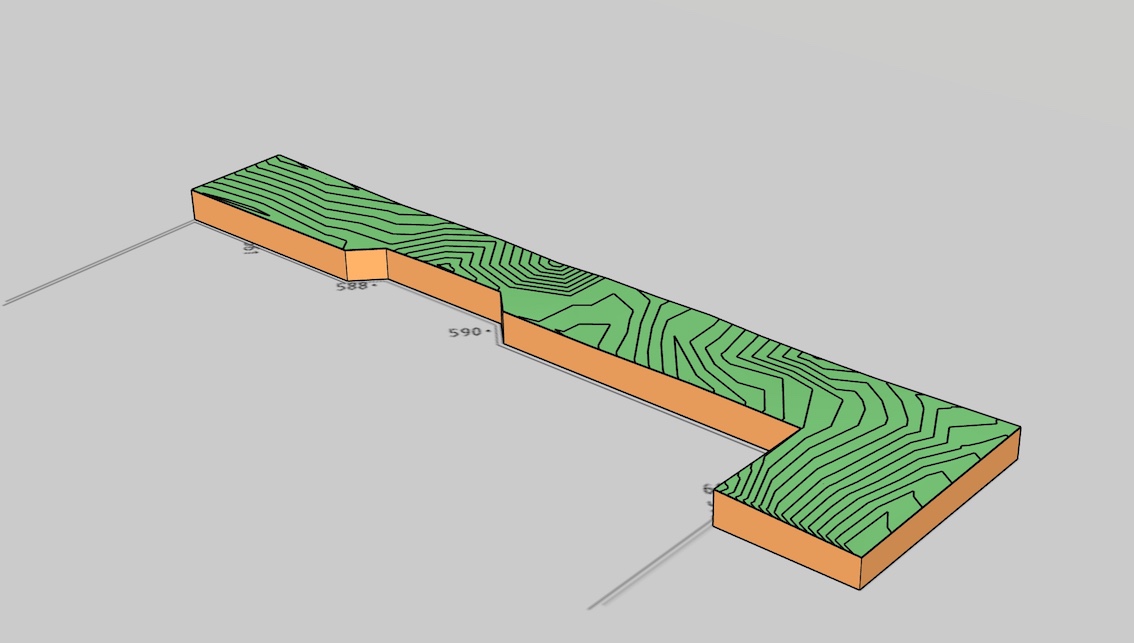
(and thanks again for volunteering that info..!)
-
Not that I know of. I'm usually working from a point that I already have a topo plan. I guess if you managed to put contours on new work it could be useful. But I find TIG's Add height from datum plugin to be useful for checking and temporary labeling. https://sketchucation.com/forums/viewtopic.php?f=323&t=22851. We do use it to mark contours as a reference while we are working on the model. It could be useful in a non-traditional format.
-
@studoc64 said:
Can I ask, is it possible have the contours labelled....?
What you can do is to
-
Generate your terrain from cloud points with isocontours
-
take the group of isocontours and generate the terrain by the other tool of TopoShaper (TerrainFromIsoContour). You'll get a more regular mesh based on quads
-
In this tool, you can generate isocontours and assign them labels.
Fredo
-
-
Now, that would be a fine thing...
I had a look through your Toposhaper tutorial, it would have been great if my process had proceeded the same way (I can certainly see the importance of saving your file with incremental names for each step when using this program....)
Should I take it that by embarking on the first process (points cloud) I have generated a 3D contour...?
I couldn't separate out any contours, so I selected my work and hit the quad mesh button.
The program proceeded, but I note that the contours were not available for any sort of management (per the tutorial).vis.

I hit the "Calculate Terrain" button to proceed. Still no contours and I say this because they always seemed to be present in your tutorial, to the point where you demonstrated repair etc.
vis.

Didn't play around with any settings, just proceeded to hit "Generate Terrain" which = Bugsplat.... several times..
It saps your energy a bit, this program, doesn't it....?
-
In TopoShaper::PointCloud, when you generate the isocontours, they are in a group inside the generated terrain. So just grab it, cut and past in place elsewhere in the model.
Then use the other tool of TopoShaper (Quad Mesh from IsoContours) and generate the terrain.
Attached is the updated model.
-
Thanks for coming back to me..
I like the idea of grabbing things and copying sideways. If I did this at each step and saved, I wouldn't have so many files in the project folder, as back up in case of crashes.. and it does just crash my end, when applying the quadmesh procedure.
As I mentioned earlier, if I can get isocontours from a points cloud, export these to and mark up in CAD, I am still ahead of the game...
Ta
Hello! It looks like you're interested in this conversation, but you don't have an account yet.
Getting fed up of having to scroll through the same posts each visit? When you register for an account, you'll always come back to exactly where you were before, and choose to be notified of new replies (either via email, or push notification). You'll also be able to save bookmarks and upvote posts to show your appreciation to other community members.
With your input, this post could be even better 💗
Register Login


Advertisement