Medeek Wall Plugin
-
To start with I will have the standard face, polygon and line wall tool.
-
I "kicked in" Hope others do as well. I hope to see it funded and move forward!
-
8 Aug Update
-
Medeek Const Library - Kickstarter Status at: 14 Aug
-
Medeek Const Library - Kickstarter Status at: 20 Aug
All or nothing. This project will only be funded if it reaches its goal by Tue, August 29 2017
https://www.kickstarter.com/projects/128644708/medeek-construction-plugin-library -
Medeek Const Library - Kickstarter Status at: 26 Aug
-
I've slowly been formulating my plan of attack for this plugin. Rather than jump right into it as I did with the truss plugin I've decided to take a step back and fully explore all the suggestions I have received.
I'm firmly convinced that I need to start with a 2D layout tool first that allows one to layout the floor plan (location of walls, door and windows) before I extrude/generate it into its final 3D shape.
One will be able to add, modify and delete doors and windows in each wall segment.
Essentially each wall segment will have its own database associated with it that stores all of the wall properties as well as all of the opening properties.
I've been putting together the algorithms for the studs and for adding in openings. Corner treatment is of importance to me and making sure that the studs are framed properly (as one would build it) is also of prime importance.
-
Each wall segment (Ext/Int wall) will have two ends or corners. The possible configurations for the wall ends/corners will be:
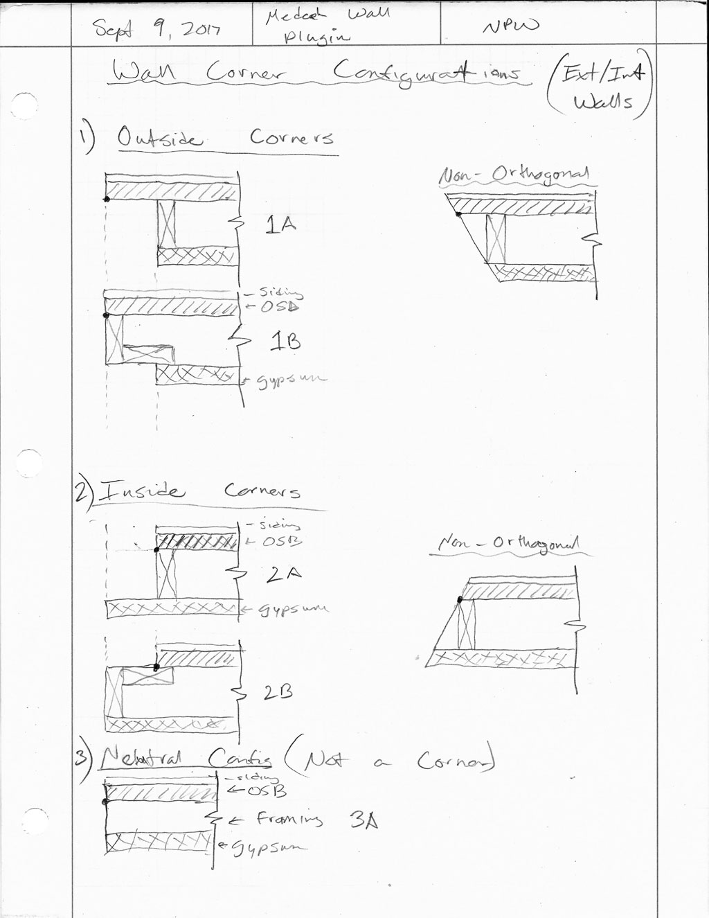
The ability to easily switch from 1A to 1B or 2A to 2B should be integrated into the plugin, at least from a framing standpoint.
-
My idea is to have a specific layer which the layout tool places all of its 2D layout geometry, something like the image shown below:
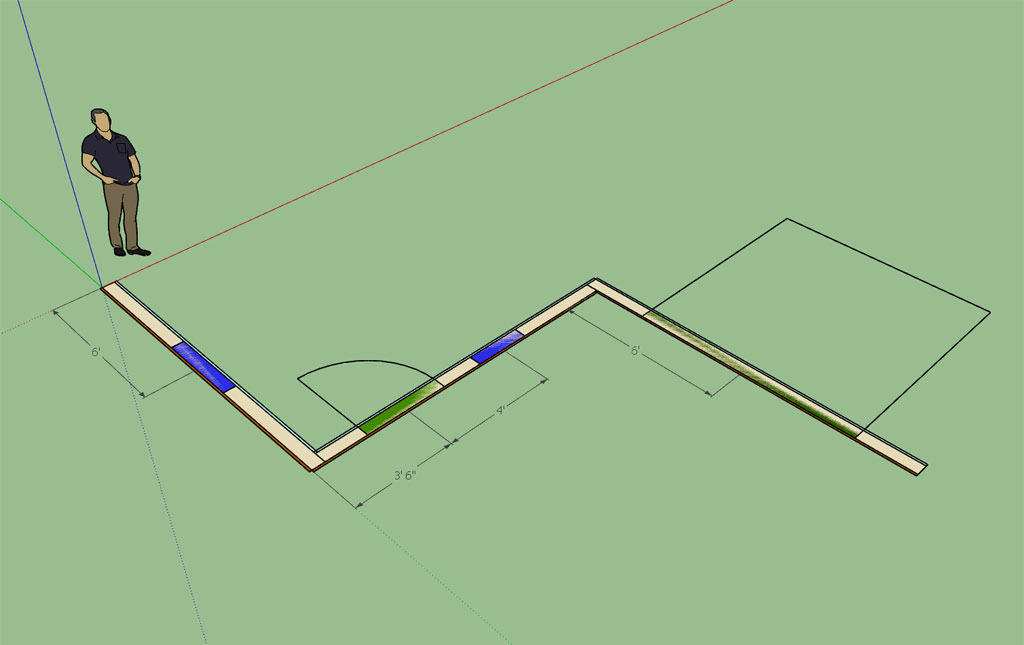
It will probably take a while to fine tune the layout tool so that it is robust and has enough flexibility to handle 99% of most wall framing situations.
View model here:
3D Warehouse
3D Warehouse is a website of searchable, pre-made 3D models that works seamlessly with SketchUp.
(3dwarehouse.sketchup.com)
My idea is color code openings (windows, doors, garage doors) for easy identification. The same holds true for wall types (Ext./Int., Int./Int.). With the walls I am thinking about providing a 1 inch strip on the exterior and interior to indicate the "normal vector" of the wall and provide a visual representation for the sheathing and gypsum.
When using the door or window tool to insert a new opening if you key in a dimension it will place the opening that dimension from the start point of the wall (the wall segment currently hovering over), hopefully speeding up the process of adding openings.
I would also like to provide dimensions from the "start point" of the wall to any openings which update dynamically when the opening is moved by the user.
Inside each opening I would like to indicate the opening size and door or window type (ie. 4050XO, 2020PIC, 3068, etc...) but I don't see an easy way to insert simple text into the model.
Once you have the floor plan put together with the layout tool, you simply hit the "Generate" icon and the plugin will then automatically generate all of the walls (framing, openings, insulation, sheathing, siding, gypsum, baseboard and moulding) and optionally insert doors and windows into all of the openings.
As the plugin matures, the plan is to provide more options for window and door options (mullions, wood vs. vinyl, dynamic components etc...) as well as increased options for wall cladding (siding, brick, cultured stone, stucco , wainscoting, pre-cast concrete accents, quoins, etc...)
Perhaps my vision is too ambitious?
Fill free to chime in if you think I'm not heading in the right direction with a specific aspect of the plugin. Ultimately the plugin is for you.
-
Hello again Nathaniel.
I find it absolutely extraordinary with all of the hundreds of accomplished plugins out there, there is no wall tool we can use effectively. Amazing really. Not even a decent double line tool (!). So here we are.
I have been waiting for a very long time to see a professional, robust and fluid design wall tool show up for SU. I am hoping yours is to be it.
Also, I believe it is absolutely essential that your design wall tool be at the vital centre of the 'construction tool' you plan with the floor/foundation and truss plugin in full support of this triumvirate.
I respectfully submit the following comments, again for your consideration, as you ramp up your wall tool coding:
@unknownuser said:
I'm firmly convinced that I need to start with a 2D layout tool first that allows one to layout the floor plan (location of walls, door and windows) before I extrude/generate it into its final 3D shape.
I believe this is the exact opposite of where you should start. We do not need a 2D layout tool. SU already has one in the form of DIBAC's wall tool.....( I use it as my (present) wall layout tool and it does an adequate job. One can duplicate a wall, but one cannot move a wall. It has to be erased to start again. The double lines fuse nicely and the walls can follow the axis and the reference line can jump on either side of a wall, but no angled walls can be created unless a protractor line is placed. Not bad really. However, I do not like its paradigm of pressing a button to lift the 2D layout into 3D with windows and doors already pre-placed as 2D/3D dynamic components. It just does not give me the flexibility or control I am looking for).
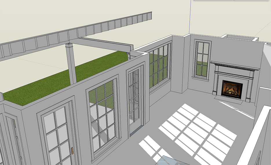
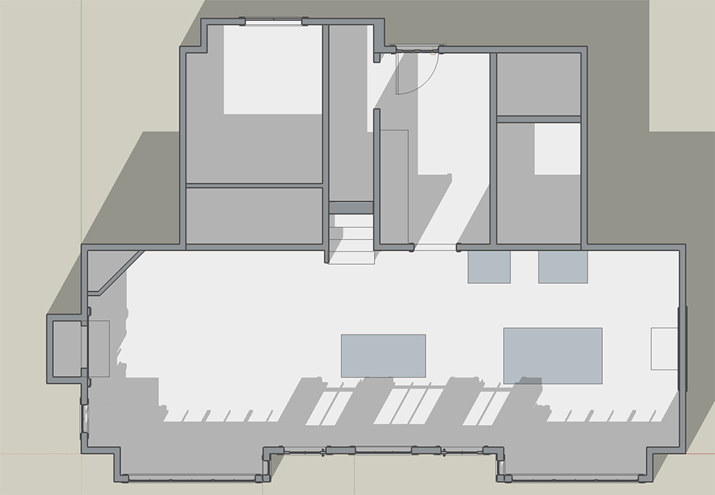
- What we need is a parametric 3D wall that we can work with as a design tool to lay out our buildings and install 3d windows and doors into each wall.
@unknownuser said:
One will be able to add, modify and delete doors and windows in each wall segment.
Yes, but in 3D as I indicate in the attached sketches.@unknownuser said:
Essentially each wall segment will have its own database associated with it that stores all of the wall properties as well as all of the opening properties.
These properties should include the ability to cut, stretch, or delete a wall, and have it fuse with its neighbour when it meets at an intersection. Eneroth's VISUAL MERGE came out recently (another brilliant plugin) and I use it to visually fuse walls at the very end of my final design conclusions. The walls do not fuse, but the coplanar lines disappear. Perfect little plugin. Not sure how you will deal with walls that need to connect and re-connect, but here is an obvious solution at hand.@unknownuser said:
I've been putting together the algorithms for the studs and for adding in openings. Corner treatment is of importance to me and making sure that the studs are framed properly (as one would build it) is also of prime importance.
I hate to disagree with you here, but I must---and my comments are similar in nature to what I said about the truss plugin as carrying too much engineering for designers. We do NOT need framing information in these walls. They should be used--at phenomenal laying out, editing, and re-editing speed---strictly for design. While it is hugely important how we lay out floor systems for finding point loads, and equally so for how truss systems will shape and carry roof loads, we do not need to educate a framer on a how a wall or headers go together. Other programs make a big deal about showing wall framing but even for them it is not necessary. As an old carpenter, I do not know any framer who needs to be shown on a drawing how to lay out a wall. Not necessary......
If, however, stud quantities are required for estimates, there are some already available for SU that extrapolate their calculations from surface area. Would that not be enough?
If corner framing details are required, I would put them into separate SU detail files to port over to Layout as required.- The ideal Medeek wall tool for us:
a. work in plan with a Z parameter pre-established and easily modifiable;
b. allow a horizontal section (at a chosen height, say 5ft) to show the cut location of a window, a 3D door w. a 2d door swing symbol at floor level;
c. be able to change reference line and thickness of a wall on the fly;
d. be able to change lengths of walls after they are placed (stretching);
e. As I say above, walls should fuse and disconnect from other walls easily;
f. Most win/door plugins work in 3d WITHIN a group. This facility has to be there with this wall tool (I use Vali's door/win tool exclusively);
g. Internal section assembly of a wall to be left to details, not inserted within the double face tool itself;
h. If there is any chance for an editable dimension line to appear when a wall is clicked this would speed up the design and editing process enormously....!
i. have a practical connection with SKALP for section cuts;
I am 'futzing' about what I want because I know this plugin is a very big deal to get right. This one is the game-changer.
Most sincerely.
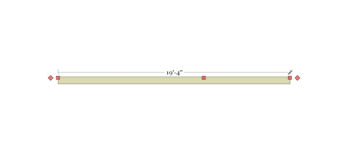
- What we need is a parametric 3D wall that we can work with as a design tool to lay out our buildings and install 3d windows and doors into each wall.
-
Our notes passed each other in space before landing seconds apart.
I will read yours with great care.
Cheers. -
As you have noted the framing is probably not necessary for the majority of the users however it may be useful or helpful for some. My thinking is to put in an global setting that allows one to toggle this feature on or off.
With windows and doors what features are you likely to edit once they are created? These are the items that come to mind off the top of my head:
- Location both horizontally and vertically (windows only).
- Size (height and width)
- Type: door (left, right, inswing, outswing); windows (slider, single hung, double hung, picture etc..)
- Advanced attributes and stylistic features.
- Delete entirely, wall must heal itself.
The idea behind the 2D layout tool is that it seems it would be easier to initially layout the floorplan this way rather than being cluttered with all the other accoutrements. Once the 3D model is created does not mean that you can no longer edit the model, having the ability to edit walls, windows and doors once they are created is pretty much a given. I agree though that this step in the plugin development is crucial to its success. If I get it wrong, it will flop, if I get it right it will be a game changer and that is the reason I have pulled back from jumping into the development headlong as I did with my Truss Plugin.
Some careful thought and planning into the mechanics and workflow of this thing is prudent.
-
I'm also starting to think about the problems associated with moving walls and how best to handle this. Not a trivial problem but I think it can be coded.
-
I've been looking at other related software and plugins to understand better what is already being done.
I've just finished watching a lengthy video on PlusSpec, it basically does everything already that I am trying to do with this wall plugin and my truss plugin. Other than the price why isn't everyone already using PlusSpec, it seems like a very comprehensive and mature product compared with my minimalistic offerings.
-
Annual subscription and a price that makes no sense. It is even more expensive than Archicad and Vectorworks per year and has dramatically less of their decades long capabilities.
And further----if, after several years of usage one decides to stop using PS, you will have lost all the capabilities you had counted on. Gone.
Equally essential, with AC and VW you can buy the program outright and NOT update if you do not care too. You can work with the version you bought for ever if you wish. It is still always inherently robust.
-
I agree that the subscription business model is a very bad idea.
My licensing follows AC and VW where you only need to renew your license if you choose to upgrade to the latest release and your one year has expired. The plugin will always work once you have a serial number. However, I still get quite a few complaints about even this business model so I am giving it some more thought.
It seems like PlusSpec is just shooting themselves in the foot so to speak. They could already be dominating the SketchUp market with their product in my opinion.
-
I've been thinking about the First and Second Menu and here is my latest revision:
First Menu:
1.) Wall Mode: Line, Polyline
2.) Wall Type: Exterior, Interior
3.) Wall Justification: Front, Center, Back
4.) Wall Height (in.): 97
5.) Wall Header Height (in.): 80
6.) Stud Size: 2x2, 2x3, 2x4, 2x6, 2x8, 2x10, 2x12, CUSTOM
7.) Stud Spacing (in.): 12,16,19.2,24,32,48, CUSTOM
8.) Stud Direction: Left, Right
9.) Start Corner: End, Outside Corner, Inset Outside Corner, Inside Corner, Inset Inside Corner
10.) End Corner: End, Outside Corner, Inset Outside Corner, Inside Corner, Inset Inside Corner
11.) Top Plate: 1,2,3
12.) Top Plate Thickness (in.): 1.5
13.) Bottom Plate: 1,2,3
14.) Bottom Plate Thickness (in.): 1.5
15.) Adv. Wall Options: YES,NOSecond Menu (Adv. Wall Options):
1.) Wall Sheathing: YES,NO
2.) Sheathing Thickness: 3/8,7/16,15/32,1/2,19/32,5/8,23/32,3/4
3.) Wall Cladding: YES,NO
4.) Cladding Thickness: 3/8,7/16,15/32,1/2,19/32,5/8,23/32,3/4
5.) Wall Gypsum: YES,NO
6.) Gypsum Thickness: 1/4,3/8,1/2,5/8
7.) Wall Insulation: YES,NO
8.) Insulation Type: PINK FIBERGLASS, YELLOW FIBERGLASS, BLOWN FIBERGLASS, ROCKWOOL, CELLULOSE
9.) Corner Framing: California, 3 Stud, 2 Stud etc...
10.) Holdowns: YES.NONote that I have eliminated the Corner offset. The amount of offset will be driven by the stud depth, however in the actual wall library (store parameters) I will include the offset for both start and end so that they can be edited independently. Right from the get go I will set this up so that one can right click on the wall panel and instantly edit any of these settings as well as add or remove window and door openings.
I'm also going to add in a holdowns advanced option which will then trigger a sub-menu which will allow one to place holdowns at each end of the wall segment.
The holdowns sub-menu (subject to change) will include the following parameters:
HOLDOWNS MENU:
1.) Holdown Type: DTT2Z, HDU2, HDU4, HDU5, STHD14, STHD14RJ, etc... (also straps ie. MSTC)
2.) Holdown Vertical Offset (in.): 0 (this allows the ability to fine tune the placement)
3.) Holdown Anchor Bolt: None, SB58-24, SB78-24, SB1-30, SSTB16, SSTB20, SSTB24, SSTB28, SSTB34, SSTB36, THD Rod, SB + THD Rod, SSTB + THD Rod (this parameter will be applied only if holdown type requires an anchor bolt)
4.) THD Rod Length (in.): 24 (this parameter applied only if an option with THD Rod is selected
5.) Holdown Placement: Start, End, Both
6.) Holdown Strap Placement: Framing, SheathingThe anchor bolt options that include a threaded rod with the anchor bolt will also include the appropriate coupler nut based on the size of the anchor bolt chosen: CNW58, CNW78, CNW1
Additionally the threaded rod diameter will be based on the holdown chosen.
As you can see there is going to be a considerable amount of logic that determines the sizing of these components.
-
The corner framing for each end of the wall panel can be set in the advanced options as well as in the global settings (default value).
This parameter can also become very important when holdowns are specified especially large capacity ones like an HDU11 or HDU14.
In these cases the end stud might be a combination of nail laminated studs (ie. 3 - 2x6) or a solid post like a 6x6 DF No. 2 timber.
There is a multitude of ways to frame a corner:
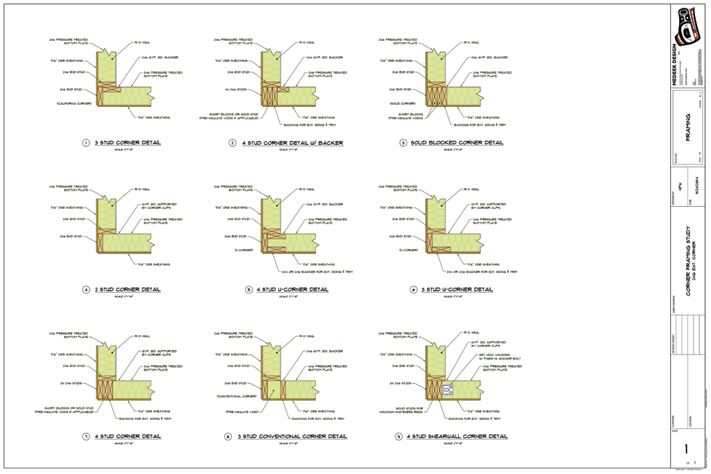
http://design.medeek.com/resources/framing/FRAMING_CORNERS.pdf
The most popular of which is probably the california corner (Detail #1)
To start I will probably go with the following options for corner framing:
- California Corner
- 1 Stud
- 2 Stud
- 3 Stud
- 4 Stud
- 4x Post
- 6x Post
When the corner is an inset or end variant it will default to a 1 Stud corner, otherwise it will default to a California Corner or whatever is specified in the global settings as the preferred corner treatment.
-
Sometimes the filler studs are in fact 3-4 short blocks distributed top to bottom.
-
Good to see traction on this essential plugin.....!
Can you tell us how you intend to cut in for windows and doors, and will we be able to use anyone else's
win/door plugin to work with your wall tool?
Cheers.
David
Advertisement


