Medeek Wall Plugin
-
@medeek said:
@pilou said:
Between versions must do uninstall the previous or install just the new over the previous ?
Please uninstall first, I think this is the safe bet, I've seen issues with installing over top of previous versions.
And re-start Sketchup after installing extension. (Seems necessary......perhaps no?)
-
@charlie__v said:
@medeek said:
@pilou said:
Between versions must do uninstall the previous or install just the new over the previous ?
Please uninstall first, I think this is the safe bet, I've seen issues with installing over top of previous versions.
And re-start Sketchup after installing extension. (Seems necessary......perhaps no?)
If you entered your serial number for the first time then yes a restart of SketchUp is required.
-
Had a question on door hardware this morning.
I should point out that within the door install menu (and door edit menu) the user can pick between seven different styles of door hardware. Currently only Style1, Style2 and Style3 are active which means that the component (.skp) file exists in the components sub-folder.
If you want to add more hardware components, just name them (Style4, Style5, Style6 or Style7) and place them in the "components" sub-folder.
At some point I will probably move the door hardware into the "library" sub-folder and provide a better system for selecting and adding additional hardware within the global settings. The current system is limited and rather primitive.
Note that Style2 is a lever handle while Style1 is a typical doorknob. Style3 is a doorknob/deadbolt combo.
-
Just for curiosity sake I gave crown molding some more thought this morning and it quickly became apparent to me that interior trim is far more complicated than I originally thought.
The problem arises when you have a long ext. or int. wall that is adjacent to multiple rooms, where multiple walls tee into this wall. Some of these rooms may have crown molding and some may not.
To make this completely parametric would require some very serious logic.
Another option would be to decouple the crown molding from the wall panels and just make a separate tool for this function.
Option C would be just to leave this venue to other plugins like Profile Builder. The problem with this option is that with baseboard and chair rail the door and window openings would have to be manually removed.
For now I don't have an optimal solution for interior trim, I will need to give this some more thought.
-
Plugin utilization breakdown:
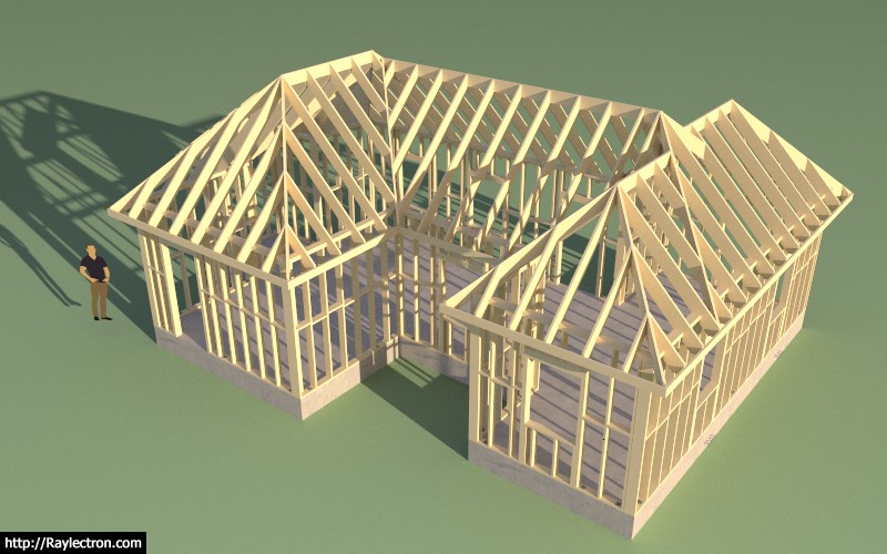
Foundation Plugin: Not parametric, slab on grade foundation, less than a minute
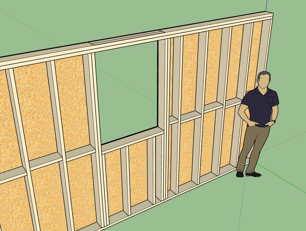
Wall Plugin: Fully parametric, exterior walls only with some doors and windows, about a minute
Truss Plugin: Rafter roof not parametric and required manual editing to complete this roof framing, approximately 30-45 minutes of trimming members with the trim tool (Truss Plugin).
Based on this test the area I am falling down in most is the roof. I need to be able to automatically create complex roofs and also have them fully parametric, this has always been the holy grail of the Truss Plugin and I have not yet achieved it.
In my mind the Wall Plugin has already surpassed the Truss Plugin in ability and functionality.
-
Cool assemby of 3 specialized plugins!

-
I really like what I am able to do with the Wall Plugin now. Granted it does have a few missing elements but overall it can throw up some walls quickly and is full parametric. My issue is really with the Truss Plugin and its inability to handle full automation and parametric design.
-
While the wall plugin has so many options to consider I can see how the complexity of truss design is difficult to cover in a plugin for all (or most) considerations. Nevertheless great work all around!
-
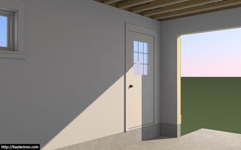
I just noticed this morning that I don't have a vertical offset for doors, funny nobody else has noticed this yet:
-
Version 0.8.4d - 07.05.2018 thru 07.09.2018
- Added a vertical offset parameter for doors that allows a door to be positioned below the bottom plate of the wall.
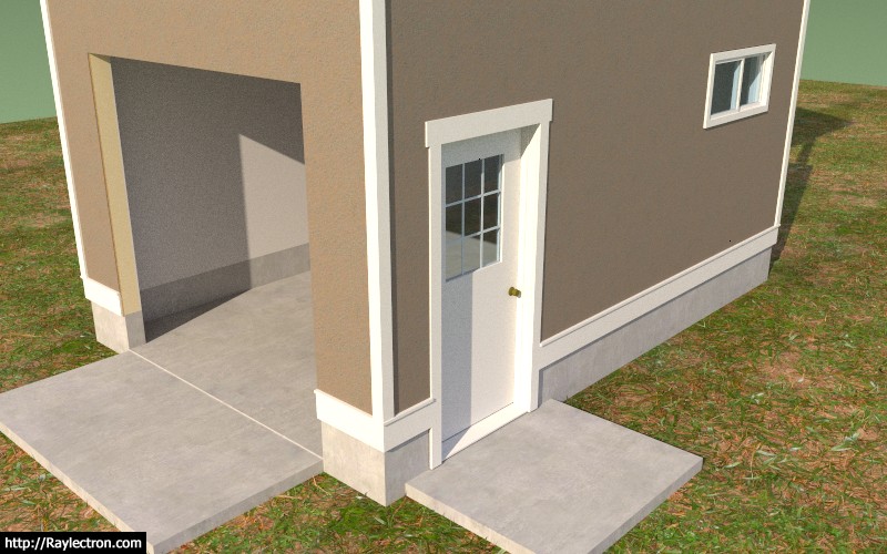
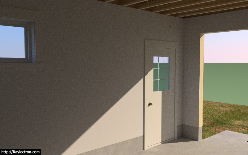
Door is vertically offset 12" into blockout in concrete stemwall.
-
To better reflect the distinction between a plugin and extension I will be re-branding the plugin and renaming it to just "Medeek Wall".
From here on out I will also be referring to it as an extension.
The entire collection of plugins will be re-branded as:
Medeek Architect - A SketchUp Extension Library
-
There may be an issue with calling the collection of plugins Medeek Architect because of the reserved status of the word architect and architecture. I'm not even sure who to contact in regard to this matter to check on any legal difficulties, but I will do some more research tomorrow.
Other ideas for names include:
Medeek Construction
Medeek Home
Medeek Arch
Medeek Designer
Medeek SU
Medeek BuildI kind of like the ring of Medeek Architect, but I don't know if it will fly.
-
There's "Chief Architect" --don't know if there's a licensed individual involved. Not the same as if you were trying to sell services as an architect but some people do get litigious and states do have widely encompassing protections on the word.
-
Medeek 3D Construction ?

-
Added the APL4 Beam-to-Column Tie per designer request:
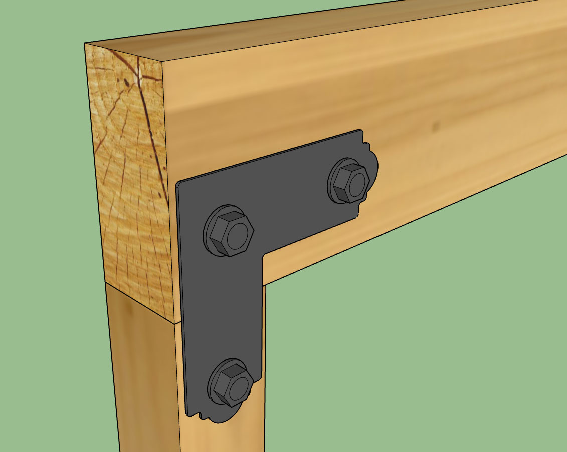
Installed in pairs with total of six STN22 decorative washers.
-
Medeek Architecture Designer?
-
Medeek AAi for Sketchup (Artificial Architecture intelligence)

-
I would put a request in for all the Simpson Outdoor Accent Connectors as well as the CPTZ Concealed Post tie. I've modeled some of these for one project but it would be great if they were incorporated into your extension (almost called it a plugin
 ).
). -
@krism said:
I would put a request in for all the Simpson Outdoor Accent Connectors as well as the CPTZ Concealed Post tie. I've modeled some of these for one project but it would be great if they were incorporated into your extension (almost called it a plugin
 ).
).I was going to add the post feature to the foundation ext. but I think I will add it to the wall ext.
To this feature I will then add the ability to include post bases and caps. Then I will add in all of various Simpson hardware for free standing posts.
-
Version 0.8.5 - 07.11.2018
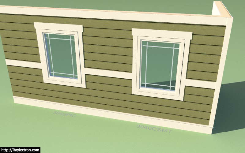
- Added the Prairie Grille for picture windows.
- Added "Casement" and "Fixed" to the window installation types, these currently are modeled identical to the picture window type.
- Added a "No Header" option for windows.
- Updated the licensing system to include a 30 day limit of the trial version.
- Added Simpson Strong-Tie APL4 Beam-to-Column Tie to the beam hanger library.
- Name of plugin changed to "Medeek Wall".
Advertisement


