Foundation Plugin
-
Now that I have stemwalls and brick ledges on my mind it seems clear that we probably need a brick ledge option for stemwall steps:
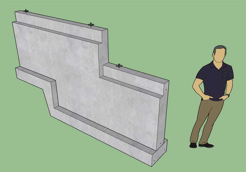
However, as I'm looking around at various examples of brick ledges combined with steps it appears that sometimes the brick ledge laps as shown in this image:

Do I need another parameter so that the designer can lap the brick ledge?
View model here:
3D Warehouse
3D Warehouse is a website of searchable, pre-made 3D models that works seamlessly with SketchUp.
(3dwarehouse.sketchup.com)
-
Version 1.4.9b - 09.19.2019
- Fixed a bug in the Layers tab of the Global Settings.
*** Critical Fix ***
This seemingly minor typo in the HTML prevents the user from saving their updated settings within the Layers tab of the global settings. I highly recommend upgrading to version 1.4.9b in order to resolve this issue.
Versions 1.4.2 thru 1.4.9 are affected by this bug.
-
First look at stemwall steps with brick ledge (and insulation):
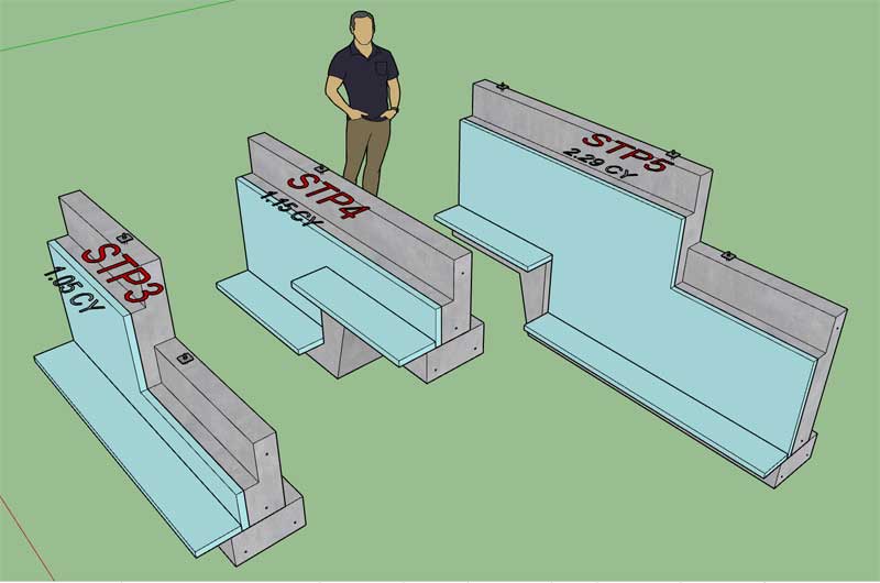
Now I just need to enable the "Ledge Lap" parameter which will allow for an overlapping of the brick ledge for Top and Double steps, obviously this does not apply for the Bottom step type.
I got back in from Utah just about a month ago. In the last four weeks I've managed to make quite a dent in this plugin (15 major updates, version 1.3.5 thru 1.5.0). I'm pretty excited with the way this plugin is finally taking shape, there is always more to do, but it is beginning to feel like a much more useful extension now.
-
Version 1.5.0 - 09.19.2019
- Added a brick ledge option for stemwall steps.
- Added a parameter which allows the lapping of brick ledges for the following stemwall step types: Top, Double.
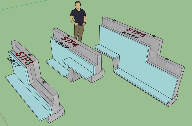
Note that the "ledge lap" parameter does not apply to Bottom steps, the step shown in the middle of the image.
The lap distance can be set by the "Ledge Lap Distance" parameter independently of the ledge height.
View model here:
3D Warehouse
3D Warehouse is a website of searchable, pre-made 3D models that works seamlessly with SketchUp.
(3dwarehouse.sketchup.com)
I would really like to see someone use the extension to model up a fairly complex project (for construction) and get a little more feedback on the weaknesses and strengths of the plugin as it currently stands.
-
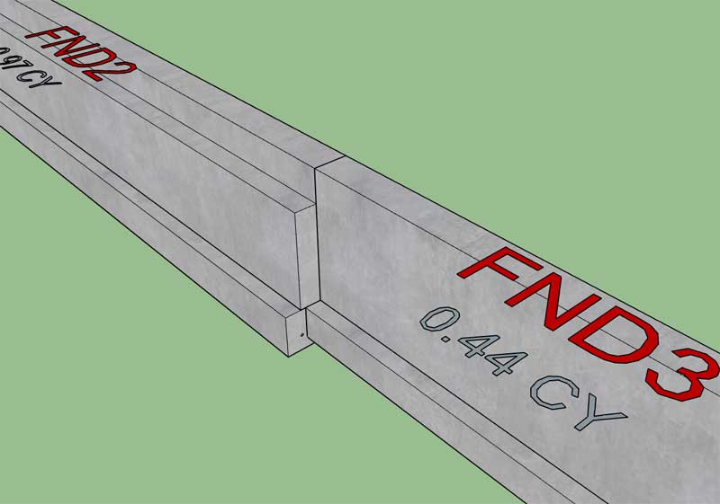
I am curious how to handle a situation where the brick ledge terminates along a linear stretch of stemwall?
Here I have a 10" stemwall with brickledge meeting a 6" stemwall without. What is typically done in this situation?
-
When you throw brick ledges into the mix the horizontal surface texture doesn't really work well:
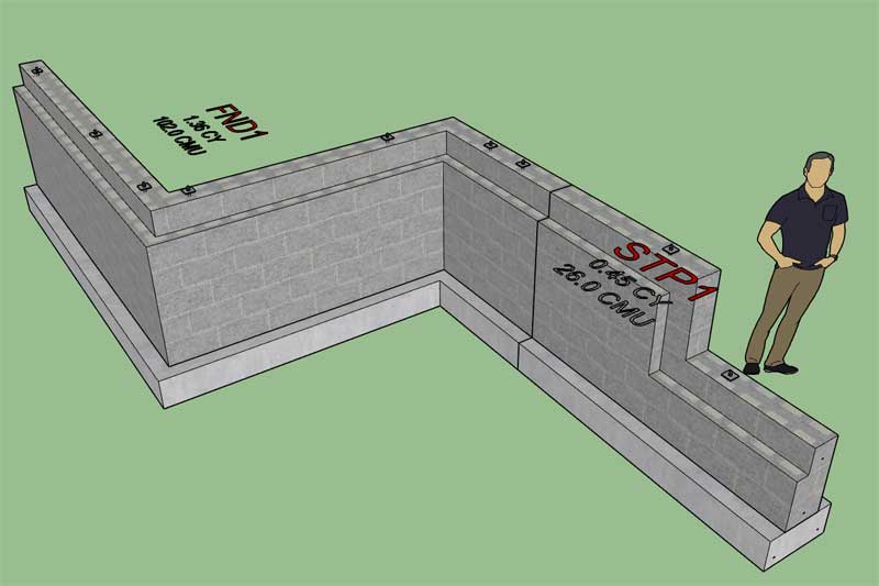
Maybe I just need to go with a more generic texture for these surfaces?
The model has a 12" CMU stemwall with a 4" brick ledge, yielding a single row of 8" block forming the final layer on the top of the wall.
View model here:
3D Warehouse
3D Warehouse is a website of searchable, pre-made 3D models that works seamlessly with SketchUp.
(3dwarehouse.sketchup.com)
-
Version 1.5.1 - 09.20.2019
- Enabled CMU blocks for spread footing piers.
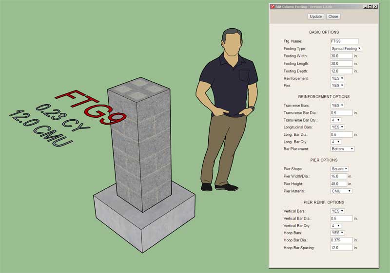
Under pier options you can select concrete or CMU block as the material type. This update is per user request.
The CMU textures seems to work best with a 16" width (square) pier. Currently rectangular piers are not an option but I may need to change that in the near future.
View model here:
3D Warehouse
3D Warehouse is a website of searchable, pre-made 3D models that works seamlessly with SketchUp.
(3dwarehouse.sketchup.com)
-
Version 1.5.2 - 09.28.2019
- Fixed a critical performance bug that affects all the modules within the extension.
*** CRITICAL PERFORMANCE UPDATE ***
If you are noticing a slowdown of the plugin performance after multiple edits to a foundation assembly or footing, this fix will resolve that issue. This issue affects all previous versions of the plugin.
-
Talking with a customer today leads me to believe that a tool for a grade beam might be useful. My current workaround is to create two separate strip footings, one on top of the other as shown:
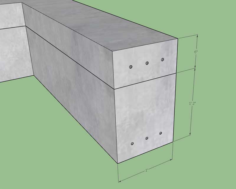
The problem with trying to use the strip footing tool to create grade beams is that it does not allow for top bar placement. Additionally, there is no FPSF option for strip footings. Let me know your thoughts on this, is this a feature you would like to see added to the plugin?
If I do add it, what other, grade beam specific, parameters might need to be added?
View model here:
3D Warehouse
3D Warehouse is a website of searchable, pre-made 3D models that works seamlessly with SketchUp.
(3dwarehouse.sketchup.com)
-
Version 1.5.3 - 12.12.2019
- Updated Slab and SOG reinforcement, replacing components with groups to increase performance.
-
Version 1.5.4 - 12.19.2019
- Enabled an "orthogonal mode" for polygon slab and SOG draw menus.
- Added the ability to delete points in the polygon slab and SOG draw menus.
Clicking the "Ctrl" key will enforce orthogonal mode while using the draw tool. Currently the orthogonal mode will restrict the user to 45 deg. increments.
While selecting the points for a foundation outline the user may accidentally select an incorrect point. By clicking the left arrow key the user can delete the previously selected point (or multiple points).
-
Version 1.5.5 - 02.06.2020
- Enabled an "orthogonal mode" for the polyline stemwall draw menu.
- Fixed a bug in the text input method of the draw menus for: polyline stemwalls, polygon slabs, polygon SOG, and strip footings.
-
Version 1.5.6 - 02.11.2020
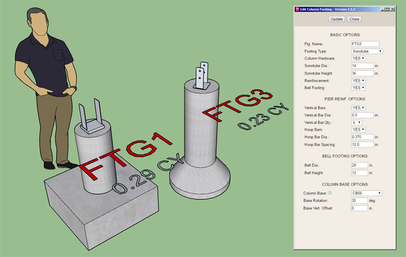
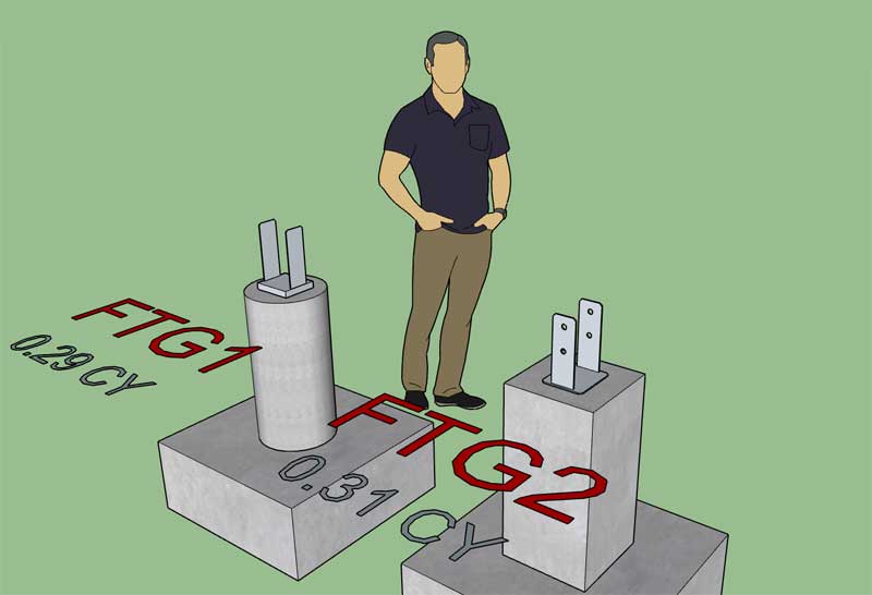
- Added an option for column base hardware for all column footings.
- Added the following Simpson column bases to the built-in library: CB66, CBSQ66
View model here:
3D Warehouse
3D Warehouse is a website of searchable, pre-made 3D models that works seamlessly with SketchUp.
(3dwarehouse.sketchup.com)
-
I've only added two (low poly) column bases thus far, obviously there are many more (just open a Simpson's catalog). If you have a specific part you would like to see added to the built-in library please let me know.
Similar to the electrical plugin, the user can simply drop their column/post base SketchUp components into the library sub-folder of the plugin to use them with the column footing tool.
The vertical offset parameter was specifically added for cast in place bolt groups so the depth of embedment can easily be adjusted as needed.
As seen in the screenshots the hardware is always centered on the footing with the rotation parameter allowing for any degree of rotation.
This update was per a customer request.
-
Version 1.5.6b - 02.16.2020
- Added the following Simpson column bases to the built-in library: CBSQ44, CBSQ46, CBSQ86, CBSQ88
View model here:
3D Warehouse
3D Warehouse is a website of searchable, pre-made 3D models that works seamlessly with SketchUp.
(3dwarehouse.sketchup.com)
-
I've had a number of requests recently for an air gap for the interior of the wall (air gap between the framing and gypsum).
It seems this air gap is typically for furring strips or possibly a foam insulation layer.
I don't think it will be much of an effort to add this additional feature but I just want to gather further feedback and see if there is enough interest in taking the time to include an extra interior air gap parameter.
Please feel free to comment or send me comments directly to nathan@medeek.com.
-
I haven't heard of anyone using that. My first thought is that we don't want air passage in the insulation layer. Perhaps they are putting a vapor barrier over the studs.
-
Version 1.5.7 - 03.04.2020
- Updated the polyline stemwall draw tool to terminate (point selection) with the "Enter" key instead of the down arrow.
- Updated the strip footing draw tool to terminate (point selection) with the "Enter" key instead of the down arrow.
I've never been really happy with using the down arrow as the termination key for the polyline stemwall and strip footing tools, it was always a placeholder until I could figure out how to use the Enter key instead. I've now enabled the plugin so that the Enter/Return key can be used. I have not disabled the down arrow key so actually either can be used at this time but eventually I will remove the down arrow key so that only the enter key will terminate point selection for the two draw tools.
-
I’m utilizing key code 36 for MacOS, however I need to verify that this is actually working for everyone as it should. If you are using the Foundation plugin on a Mac please download this latest version and let me know if the Enter key will now allow you to terminate a polyline stemwall.
-
After some further testing I think I will switch from the Enter key to the End key to terminate point selection. The problem with using the Enter key is that it conflicts with the manual entry of a segment length.
Advertisement


