Fails to make faces - Sketchup 2014
-
 Hello there,
I'm sure you have seen plenty of newbies asking this question, but I haven't been able to find an answer.
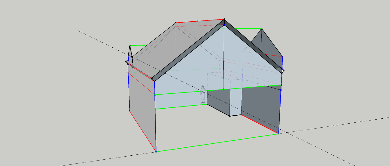
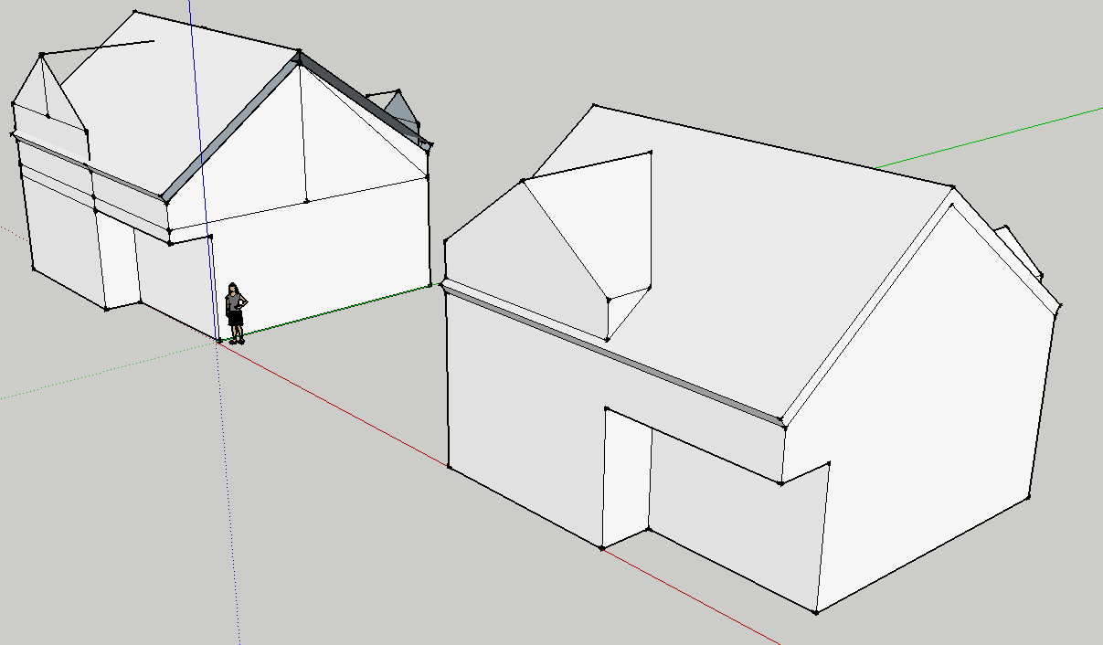
I am making a simple model of a house - 4 walls, 2 gables, 2 dormers (one with a balcony). I am still drawing walls and roof, no windows or doors yet.
Problem is, Sketchup does not put faces on all 4(or more)-edged enclosed loops. I tried the "styles>edges colored by axis" and at least some of the edges which do not get faces appear to be aligned with the axes, so they are coplanar. I have tried the "utilities/Create face" plugin, the "Suforyou/Make faces" plugin, the "Weld" plugin, and the last one I tried - but it very often crashes Sketchup - is the "Edge Tools2/find edge gaps / close all edge gaps" plugin. I also tried scaling up the model, even though its sides are several meters long in normal scale, buy with no luck.
None of them works.It is very frustrating. I do not understand why Sketchup does not have some built in tolerances so as to allow slight deviations from the co-planar requirement, and why it will not connect all lines which seem to be ending very near to each other, especially since they were all created with the "Endpoint" inference lighting up when drawn.
Also, I am running Sketchup 2014 on Widnows XP. It crashes all the time. Is this normal ?
Any suggestions ?[size=100:19o8l0of]****[/size]
-
Could you share the SKP file? It would be much easier to identify what is going on.
One test you can do is to draw a diagonal line between corners of your rectangular loops. If faces are created, you'll know that not all edges are coplanar. Color by Axis can be useful but it isn't a perfect indicator of planarity of edges due to the tolerances in SketchUp.
Another way to check is with the Text tool. Set precision very high and place labels at the points on the corners. The labels will give you the coordinates of the points. You should be able to identify if one or more points are out.
-
Here is the file (V.skp attached). Advance thanx to anyone willing to spend time to review it.
-
@redneckus said:
It is very frustrating. I do not understand why Sketchup does not have some built in tolerances so as to allow slight deviations from the co-planar requirement, and why it will not connect all lines which seem to be ending very near to each other, especially since they were all created with the "Endpoint" inference lighting up when drawn.
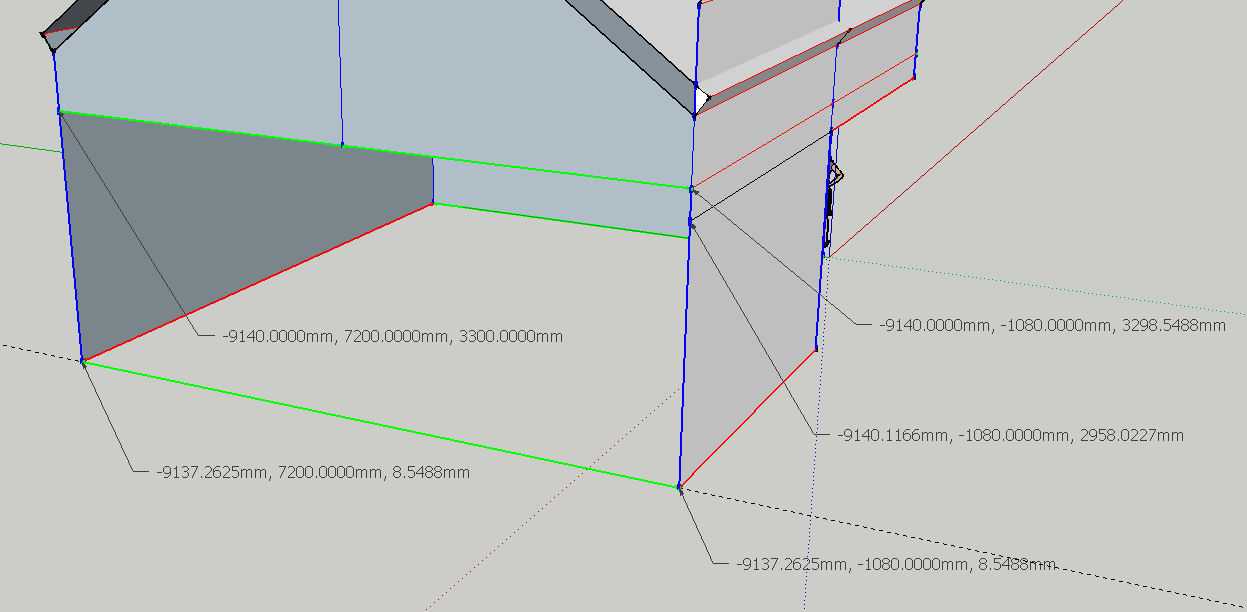
There are tolerances built in. You just didn't get close enough to them. I did what I suggested to you and got the coordinates of the points surrounding the big hole. Look at the X-values. Normally I would expect all of them to be the same but they aren't. That extra point at the end of the black edge on the right is a problem, too.There's a similar issue with the bottom loop of edges.
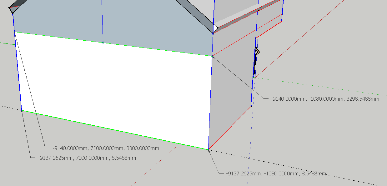
I removed the black edge on the right and replaced the vertical edges on the near corner with a single, straight edge and the face filled in.It looks to me as if you could do with spending some time on the basic tutorial videos at the SketchUp site. With the right techniques you could avoid all of these problems.
@redneckus said:
Also, I am running Sketchup 2014 on Widnows XP. It crashes all the time. Is this normal ?
No. It's not normal. Typically when we see these reports, the problem is due to a graphics card driver that doesn't handle OpenGL properly. You might try turning off Hardware Acceleration in Preferences. Check for driver updates, too.
-
Dave R,
I do not have an extra graphics card, only whatever my P5G41T Asus motherboard comes with, running an Intel Core 2 Duo E6300/1866MHz/LGA775 with 2GB DDR3.
I turned off hardware acceleration as you suggested, and it promptly crashed on the third attempt to use the text tool. -
Thanks many, Dave R. I understand your advice and will do my best to heed. But I still feel like protesting to the Sketchup designers, as it is not up to me to "get close enough to them" when joining two edges based on point or edge inferences. It should be Sketchup's job to do the joining in the same plane. This is bad behaviour, as inferences do not allow the user to "get close", they are supposed to be spot on.
Thanks for the hint on the text tool, I was not aware it gives coordinates. I tried the "utilities/Query tool" instead, I think from Smustard, but for some reason I did not think of using it to verify co-planarity in this case.
I also had tried playing with the position of the extra point in the upper right corner which you removed, by moving it back and forth along the red axis until it snapped based on the inference which verified that it was sitting on the blue axis, as did the point above it, but it still would not make the face. I suppose I should have tried moving it along the green axis too, by creating a guide maybe, but I did not think of it. But since it was vertically located on the blue axis, as were all other points according to the "Style/edge colors by axes" choice, I consider this to be a Sketchup bug.
Now, compared to this face, the ones on the roof edges which are not supposed to line up with pairs of axes, will be a b!#ch to fix.When it comes to tolerances which you say Sketchup DOES have when it checks co-planarity, I wish I could adjust them to fit my needs. I am wondering if using a relatively small but finite snap distance and angle will make my life easier from that point of view.
-
I don't know what to tell you since you are convinced this is a bug. SketchUp's inferencing does work well to guide you in setting out the edges and getting end points in the right location. I work to much higher precision than is needed to draw a building and I find it works very well.
To be honest, I think much of the problem is due to the way you are working. Instead of trying to fix this model, why not start over? Draw the footprint on the ground plane and use Push/Pull to extrude it upward to make the walls. If you've drawn the foot print flat on the ground plane, the walls will be perpendicular and you will get faces as needed.
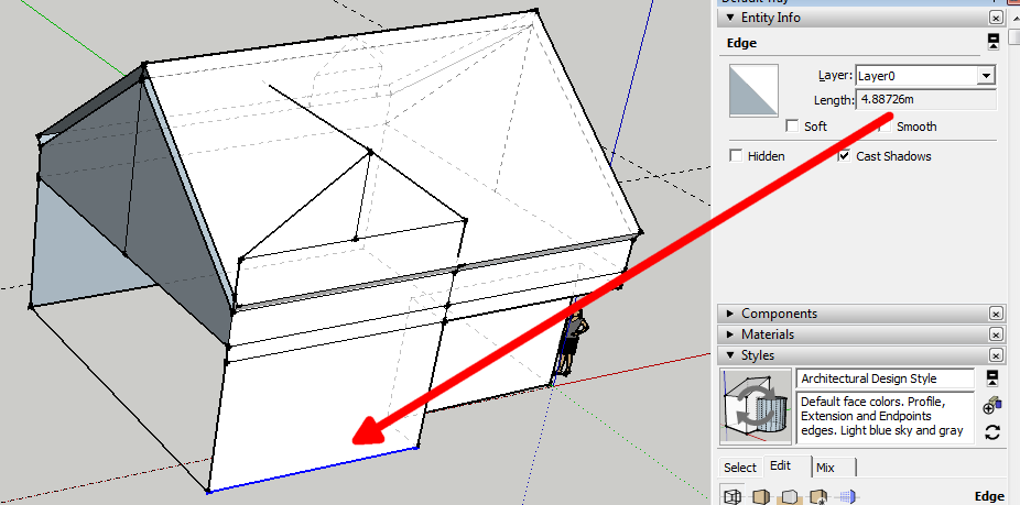
It'll be easier to start over than repair what you've got. Edges don't seem to be of the correct length. For example, is this edge at the bottom of the bump-out correct?
I quickly redrew the house. I had to guess at some of the dimensions because there are many edges in your model that seem to be incorrectly sized.
-
Dave R,
this is a model I made from photo matching the picture of a house, that is why I am not starting from a footprint plan on the ground. I suppose I could have, since I have a floor plan of the ground floor, though I still have to measure distances with a ruler on paper, but I might not have it when I try it on another building or object. This also explains the odd edge sizes you are observing.
I suppose the best way to proceed when a floor plan is available is to forego the photo matching all together and make the model in the way you are suggesting from the ground up, then import the picture and adjust the camera view and scale so as to match the picture, then proceed with copying textures from the picture to the model.I will do as you suggested, thank you very much for all the help.
I just saw that you redrew the house, thanks a lot, I will download the file and try to make use of it, but my objective was not to make you do the work for me but to understand how to do it on my own.
Thanks again for all the good will.
-
In the very end of things, I think SU should have a command to force making of a face among 4 or more points, even if it would have to create some hidden geometry - break it up to triangles, though I would prefer that it would force the 4 points into a coplanar position upon the user asking it to. Then, even with a non planar face, it should allow people to extrude out that face in some kind of user defined or automatically calculated direction (as a mean vector maybe of some geometry ending at those forced-coplanar points definig the face).
All this to withing user defined tolerances, I think would work like a charm. As it is now, judging from the number of people running into this problem, it has people chasing their tails for no apparent gain due to perceived "good practices" in some programming paradigm.
Hello! It looks like you're interested in this conversation, but you don't have an account yet.
Getting fed up of having to scroll through the same posts each visit? When you register for an account, you'll always come back to exactly where you were before, and choose to be notified of new replies (either via email, or push notification). You'll also be able to save bookmarks and upvote posts to show your appreciation to other community members.
With your input, this post could be even better 💗
Register Login


Advertisement