sketchucation logo sketchucation
    • Login
    ℹ️ Licensed Extensions | FredoBatch, ElevationProfile, FredoSketch, LayOps, MatSim and Pic2Shape will require license from Sept 1st More Info

    Hourglass Helix?

    Scheduled Pinned Locked Moved SketchUp Discussions
    sketchup
    24 Posts 5 Posters 2.5k Views 5 Watching
    Loading More Posts
    • Oldest to Newest
    • Newest to Oldest
    • Most Votes
    Reply
    • Reply as topic
    Log in to reply
    This topic has been deleted. Only users with topic management privileges can see it.
    • Dave RD Offline
      Dave R
      last edited by

      Why didn't you ask for a varying pitch in the first place? Do you want BOTH varying pitch AND the "hour glass" shape?

      Give real specific dimensions.

      Etaoin Shrdlu

      %

      (THERE'S NO PLACE LIKE)

      G28 X0.0 Y0.0 Z0.0

      M30

      %

      1 Reply Last reply Reply Quote 0
      • pilouP Offline
        pilou
        last edited by

        Helix Along Curve πŸ˜‰

        Frenchy Pilou
        Is beautiful that please without concept!
        My Little site :)

        1 Reply Last reply Reply Quote 0
        • pilouP Offline
          pilou
          last edited by

          See my previous old post for draw your curve! πŸ˜‰
          Some tricks inside!
          http://sketchucation.com/forums/viewtopic.php?f=79%26amp;t=49558#p445823

          Frenchy Pilou
          Is beautiful that please without concept!
          My Little site :)

          1 Reply Last reply Reply Quote 0
          • pilouP Offline
            pilou
            last edited by

            http://www.drawmetal.com/download πŸ˜‰
            Build the Volume first then deform it by Fredo Tool!

            • Fredo Scale Box Scaling (+SHIFT No Uniform) + Box Tapering + Box Stretching (+ F4) and you can draw any sort of volume helicoidal!

            http://s6.postimg.org/xs4tm0mmp/grillage.jpg

            Frenchy Pilou
            Is beautiful that please without concept!
            My Little site :)

            1 Reply Last reply Reply Quote 0
            • B Offline
              BallBearing
              last edited by

              Perhaps I managed to make the correct helix, but sadly now I cannot get it to work with the curviloft correctly. First image helix. Second helix made of half circles. Not good, but the closest what I have.

              helixCurviloftNotOk.png

              WormNotOK.png

              SketchUp, 3D printing stuff and more:
              http://www.youtube.com/user/CinemaTablet

              1 Reply Last reply Reply Quote 0
              • B Offline
                BallBearing
                last edited by

                Perhaps I found the correct option for curviloft. I have to think and try more...

                CurviloftPerhapsOkHelix.jpg

                SketchUp, 3D printing stuff and more:
                http://www.youtube.com/user/CinemaTablet

                1 Reply Last reply Reply Quote 0
                • B Offline
                  BallBearing
                  last edited by

                  Edit: Uh! I was fool or too tired. I do not need to make the cut. The helix path is already hourglass shape and pitch growing and valid for curviloft.

                  Sorry! First I needed just the hourglass helix and then I found that I need variable pitch also. Yes I need both. Thank you pointing to the Helix along curve! At first it looks like that plug-in can do the thing If I do a one variable pitch helix using different length lines, then copy and scale it down 0.5 red&green axis. And then make curviloft faces along the paths cutting the hourglass and leaving a path which is a helix with hourglass shape and variable pitch.. I will try.

                  hmm what is the degrees option in Helix along curve plug-in...?

                  SketchUp, 3D printing stuff and more:
                  http://www.youtube.com/user/CinemaTablet

                  1 Reply Last reply Reply Quote 0
                  • B Offline
                    BallBearing
                    last edited by

                    Edit: Uh! I was fool or too tired. I do not need to make the cut. The helix path is already ok hourglass shape and pitch growing and valid for curviloft.

                    Now thinking how to get the the path or shape helix turn tighter or more along the hourglass body, perhaps just more sections? I have to learn better this helix along curve plug-in.

                    HelixHourglassPathOpen.jpg

                    SketchUp, 3D printing stuff and more:
                    http://www.youtube.com/user/CinemaTablet

                    1 Reply Last reply Reply Quote 0
                    • pilouP Offline
                      pilou
                      last edited by

                      Maybe this can help you! πŸ˜‰

                      Loft along a Vector by the genious Projection By Didier Burr
                      Joint PushPull Interactive by Fredo

                      http://s6.postimg.org/guo6j56s1/Mini_tuto.jpg

                      ...or Curviloft! πŸ˜‰

                      Frenchy Pilou
                      Is beautiful that please without concept!
                      My Little site :)

                      1 Reply Last reply Reply Quote 0
                      • pilouP Offline
                        pilou
                        last edited by

                        πŸ˜„

                        http://s6.postimg.org/whffwikk1/vers.jpg

                        Frenchy Pilou
                        Is beautiful that please without concept!
                        My Little site :)

                        1 Reply Last reply Reply Quote 0
                        • B Offline
                          BallBearing
                          last edited by

                          Thanks! I check them. I still have about 0.2mm "error" on radius with curviloft.

                          SketchUp, 3D printing stuff and more:
                          http://www.youtube.com/user/CinemaTablet

                          1 Reply Last reply Reply Quote 0
                          • C Offline
                            CAUL
                            last edited by

                            Maybe Flowify can be of help here.

                            The spiral can be turned into a quad surface with "Extrude Edges by Vector" from TIG's extrusion tools. Just extrude the spiral edges along the blue axis up and down. After that the worm can be mapped onto the quad surface using Flowify.

                            A problem here is that since the spiral's radius is variable the vertex normals in the quad surface does not extend radially from the spirals center. This means that the distance between two revolutions in the spiral is not retained at the tip. The difference in this case is <1%.

                            In the upcoming version of Flowify (2.0) it will be possible to explicitly set the normals at each vertex. The image below shows the setup. All normals extend radially from the spirals center and this aligns the geometry at the tip with the geometry at the base between revolutions. The last image shows the difference in a section cut for three consecutive revolutions.


                            Flowify 1.1 setup


                            Flowify Result


                            Flowify 2.0 (not yet released) setup


                            Difference between Flowify versions


                            Flowify Setup skp

                            1 Reply Last reply Reply Quote 0
                            • B Offline
                              BallBearing
                              last edited by

                              There's another thing too. The tooth has to point to the center of the worm wheel. So I have tried curviloft follow spiral path and tooth faces oriented to the center. No success yet. So the path is not correct then.

                              GloboidWormToothPointsCenter.jpg

                              SketchUp, 3D printing stuff and more:
                              http://www.youtube.com/user/CinemaTablet

                              1 Reply Last reply Reply Quote 0
                              • C Offline
                                CAUL
                                last edited by

                                This is an intriguing problem. Here's another take.

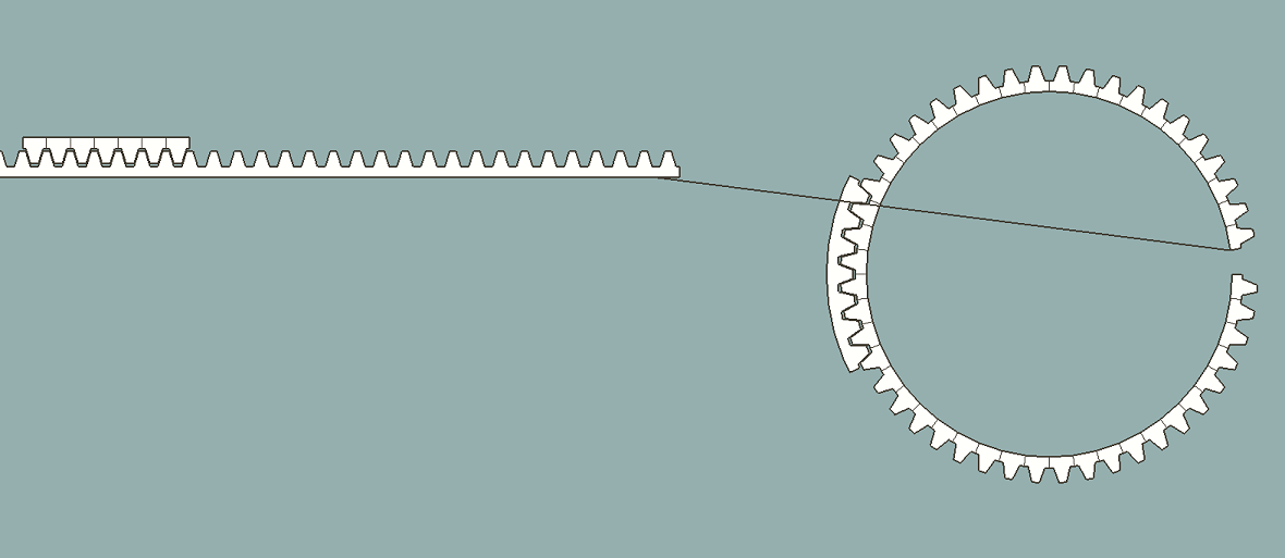
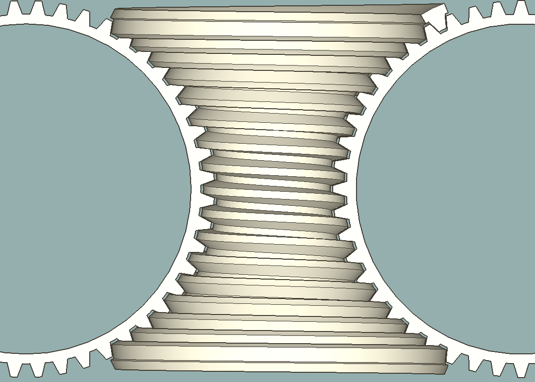
                                The first image is a flat setup for flowify and a flowify output which is a gear and a profile for the worm.

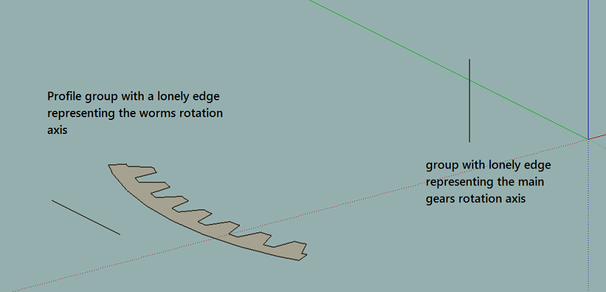
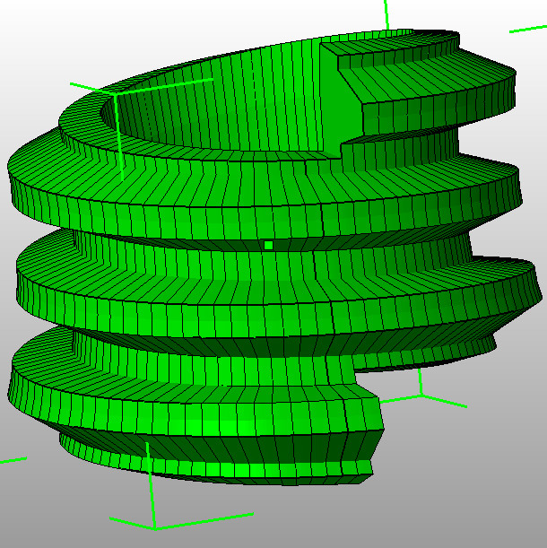
                                The next image shows a setup for a tiny custom script (attached below). The script takes two groups as input:

                                1) A group with a single edge representing the rotation axis of the
                                main gear.

                                2) A group containing the worm profile AND a lonely edge representing the worms rotation axis.

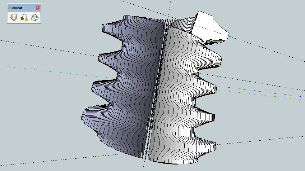
                                The script itself has two internal parameters at lines 49 and 50. Those are the number of cogs on the main gear and the number of circle segments for the worm.

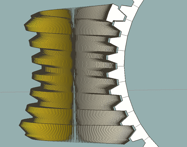
                                To run the script, open it in a text editor, set the parameters and save. Then select the two input groups, copy and paste the code into the ruby console and press enter. The result for 48 cogs on the main gear and 192 segments in the worm can be seen in the last image. The output is just profiles that have to be merged manually with Curviloft.


                                FlowifySetup.png


                                ScriptSetup.png


                                worm192profiles.png


                                wormScript.rb


                                WormIII.skp

                                1 Reply Last reply Reply Quote 0
                                • C Offline
                                  CAUL
                                  last edited by

                                  Some final observations and additions.

                                  A skinning method is added to the script so most faces are created automatically. However, since adding geometry with the internal add_face method does not merge stuff properly the resultant group needs to be exploded and regrouped. This will ensure a proper merge. Some holes need to be filled manually. Also, the worm profile must consist of exactly one face for the skinning to work.

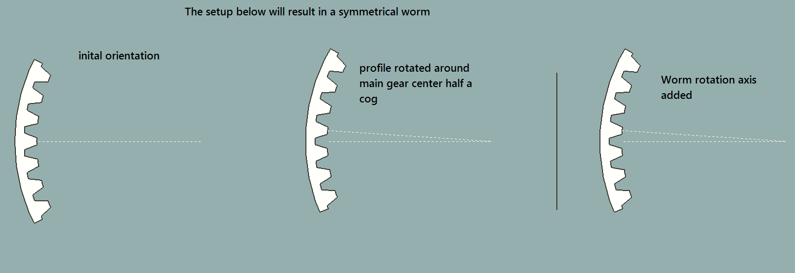
                                  When creating a worm the profile will rotate one cog around the main gear center. So, a symmetrical helix requires the profile to be rotated around the main gear center half a cog in the opposite direction. The rotation axis for the worm should be added after this procedure.


                                  SymmetricalSetup.png


                                  Helix.png


                                  wormScript.rb

                                  1 Reply Last reply Reply Quote 0
                                  • B Offline
                                    BallBearing
                                    last edited by

                                    Very nice script! Something like this, I thought, but would be painful to do "manually". So the profile has to be rotated. 40 tooth gear 4.5 (9/2) degrees etc. That's perhaps because my own profile test went horizontal and crazy mess?

                                    Naturally the worm wheel has a helix angle. Now to think where and how to cut the ends... I got the holes fixed with just automatic settings in NetFabb. There's many globoid worm tutorials in the web that seem to be erroneous, Solid works etc. Perhaps this script etc. is one quite correct way... Very nice!

                                    WormNetfabbCloseHoles.jpg

                                    SketchUp, 3D printing stuff and more:
                                    http://www.youtube.com/user/CinemaTablet

                                    1 Reply Last reply Reply Quote 0
                                    • B Offline
                                      BallBearing
                                      last edited by

                                      This came out from involute gear plug-in profile (60 Tooth). Thanks CAUL! I hope that I can soon proceed to a 3D printed piece & real world test.

                                      60T-Involute-Profile-Worm.jpg

                                      SketchUp, 3D printing stuff and more:
                                      http://www.youtube.com/user/CinemaTablet

                                      1 Reply Last reply Reply Quote 0
                                      • 1
                                      • 2
                                      • 2 / 2
                                      • First post
                                        Last post
                                      Buy SketchPlus
                                      Buy SUbD
                                      Buy WrapR
                                      Buy eBook
                                      Buy Modelur
                                      Buy Vertex Tools
                                      Buy SketchCuisine
                                      Buy FormFonts

                                      Advertisement