Need help with "solid tools"
-
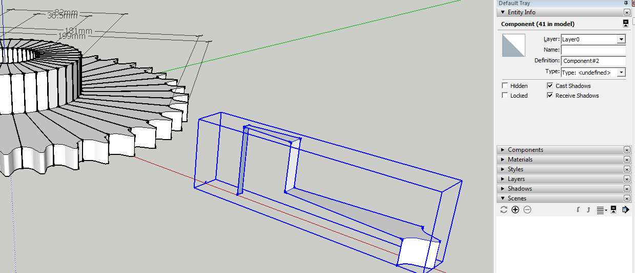
Hi all, looking for a little bit of help I have been using sketchup for a while now but have just started using it for work, am looking for a little help on the attached file. I am having trouble using "solid tools" so I can remove all the lines on the sprocket I have made. Any help/advice would be greatly appreciated.
-
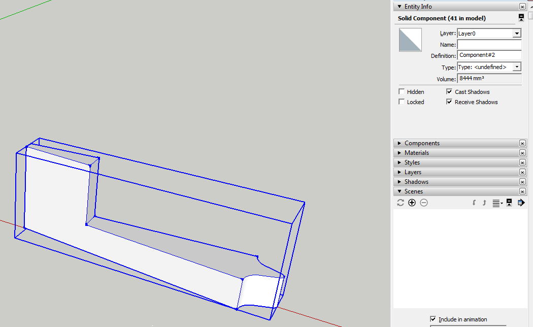
In order to use Solid Tools, your components/groups need to be solid. Yours aren't.
To be considered "solid" every edge must be shared by exactly two faces. No more, no less.
After finish adding faces to close the shape and delete that extra little edge near the center of the sprocket, the component will be "solid".
You also need to correct the face orientation as I have so white front faces are out. These are just fundamental SketchUp things so nothing special or advanced here. Just the Line tool and Eraser.
You also need to close up the gaps between the components. Since they aren't in contact with each other, you can't join them. After you have them solid and all properly in placed, you should be able to run Outer Shell to combine them.
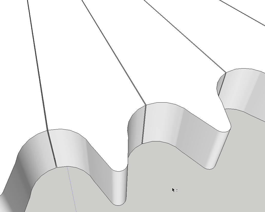
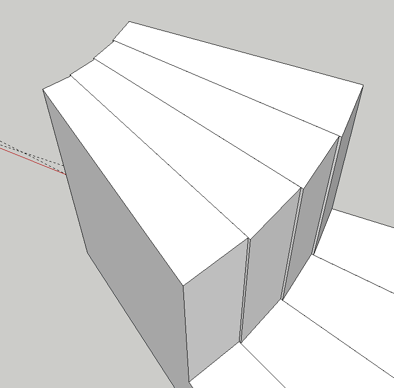
My guess is you'll also need to fit the hub area and the bore. When the components are put together so their sides match up, you get this stepped thing going on near the center.
-
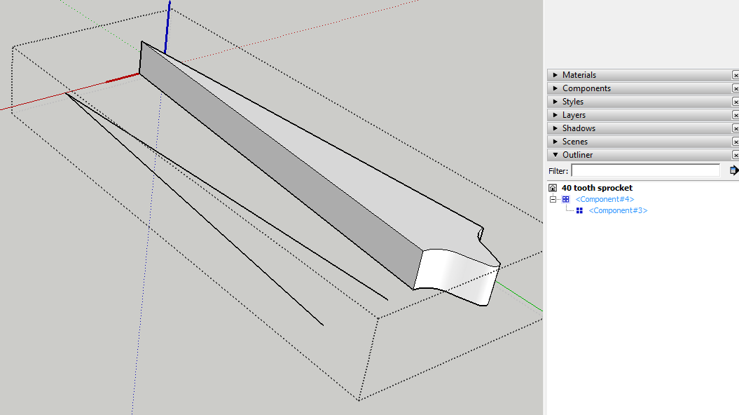
ok thanks for your help so I have started again but I have been pulling my hair out trying to fix this "nested Instance" for AGES not really too sure what it means or how I fix it any ideas how I fix this???
cheers
-
"Nested" means that you've got multiple entities within the component or group wrapper. In your case you have Component#3 wrapped up with some other edges and faces in the Component#4 wrapper. You can see that easily if you use Outliner. I moved it away from the loose geometry to make it easier to see. Delete Component#3 and Component#4 will be marked as solid.
Although you can make your sprocket this way, I'm not sure why you would. It seems to me you are adding unneeded steps. Or is it just for the practice?You might find this easier.
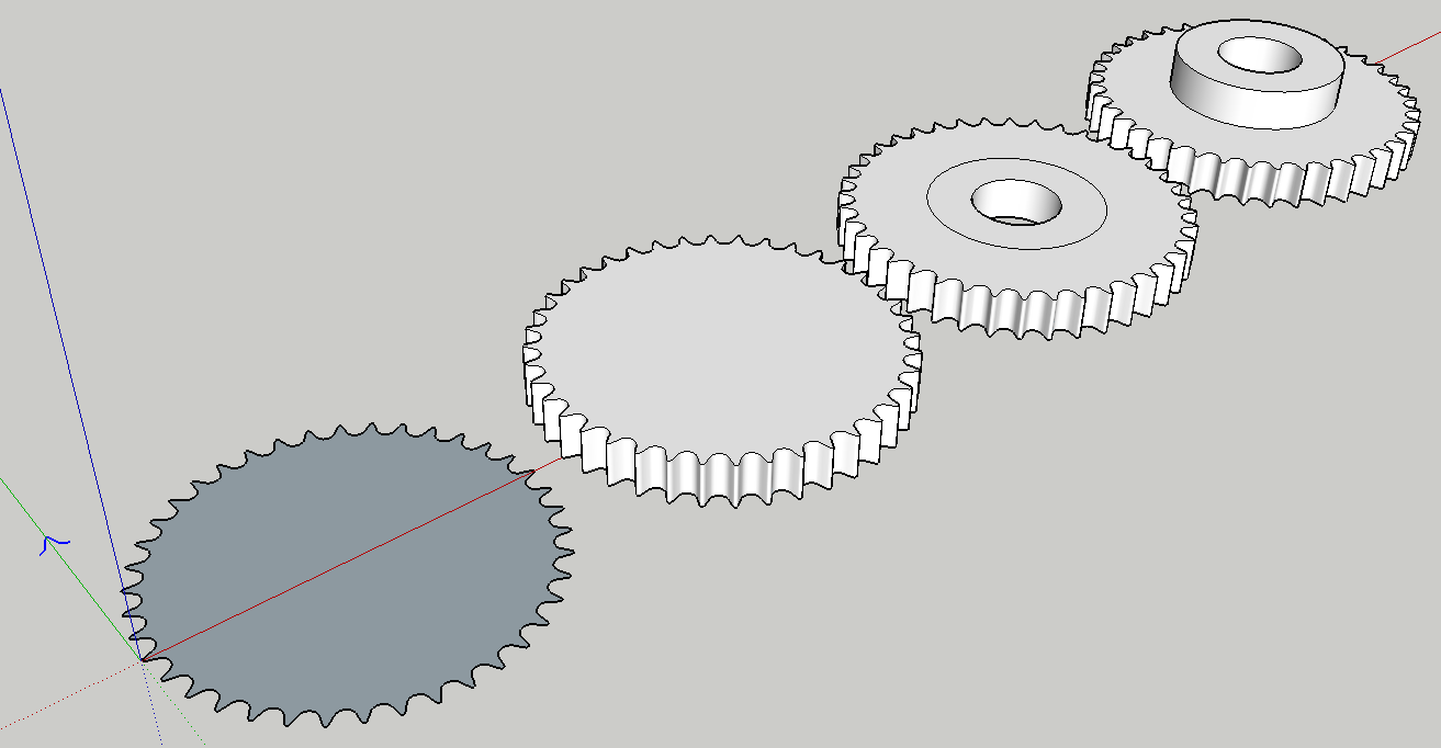
From left to right:
Draw the tooth profile.
Copy/Rotate it around to create the rest of the teeth. Trace one line segment on the edge with the Line tool to get the face.
Push?Pull to thickness.
Draw circle at center to define hole. Draw an additional circle to define the outside diameter of the hub. Push the hole through.
Pull the hub up as needed.Working around the origin for this entire process makes it easy but I think you already know about that.
-
thanks again for the reply I ended up downloading cleanup and it fixed the error for me, yeah doing it this way was for practice trying to get a bit more accustom to sketchup.
-
you make tracing sound so easy LOL been trying for half hour haven't got it right once LOL keep running out of room on the mouse pad and drawing everywhere
-
@lampy said:
you make tracing sound so easy LOL been trying for half hour haven't got it right once LOL keep running out of room on the mouse pad and drawing everywhere
Not sure what you mean in reference to this sprocket.
I work on a mouse pad space about 6 x 8 and it works for me. The mouse only needs to move about 5 inches left and right for full side to side travel of the cursor.
-
The only place I see tracing mentioned is to trace an edge to trigger SU to form a face on your tooth layout. Or am I missing the point (or the joke)? Dave's method looks good. So you just draw the tooth with arcs etc. Have to do some math for the number to complete the circle, angle etc. (but I imagine you have all that down). When you copy /rotate the tooth outlines tip to tip and they complete a closed shape, SU needs an edge (just a segment) to be traced with the line tool to cause the face to form.
-
Ahh... That's it. I was thinking of something more complicated.
Peter is right. I only meant for you to trace one line segment on the edge. Zoom in close and you'll see the segments.
Hello! It looks like you're interested in this conversation, but you don't have an account yet.
Getting fed up of having to scroll through the same posts each visit? When you register for an account, you'll always come back to exactly where you were before, and choose to be notified of new replies (either via email, or push notification). You'll also be able to save bookmarks and upvote posts to show your appreciation to other community members.
With your input, this post could be even better 💗
Register Login


Advertisement