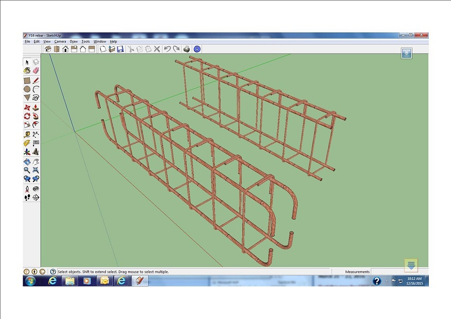
Scalable rebar cage dynamic component
-
I've being trying to design 2 dynamic components of rebar cage (iron rod cage for reinforcing concrete). One pillar and one beam. The cross section of the spacers is 225mm x 225mm. I have made an attempt (see the embedded file) in which i was able to accurately scale the spacers for the beam to scale from both ends along its lenght. However, I need assistance on the following:
-
Creating a 2 feet overlap of each of the main rods whenever the lenght of the rods exceed 20 feet (which is the standard lenght of a rod in my part of the world).
-
I want to be able to select the height of my rebar for beam by having two options of heights (225mm and 450mm).
-
I want to have two options for the thickness (diameter) of the rods - 12mm and 16mm (my attempt is in 12mm diameter rod).
-
I want to be able to select the interval of the spacers as options of 8", 9", 10" and 12"
I will appreciate assistance from anyone. Please make it compatible with Version 8 of Sketchup. Thank you in anticipation of your prompt and accurately response.
[img]C:\document\pillar%20&%20beam.jpg[/img]
-
-
Essentially, a copy of the Iron Rods group should be one 20' (or shorter) section right? And each 20' section has an overlap of 2' on each side (minus 4' for the two ends which do not overlap with anything). So I think this should work to calculate the correct number of groups of Iron Rods:
Copies = INT((Reinforcement!LenX-IF(Reinforcement!LenX>20, 4, 0))/16)Then calculate the position in X of the groups:
X = COPY*18And finally the size (bear in mind that the final rod will be less than 20'
LenX = IF(COPY=Copies, Reinforcement!LenX-Copies*20, 20)I think this all should work anyways, I'm not testing this as I go. Feel free to correct me, anybody.
Then you just need to change the position of the rods in alternate Iron Rods groups. Here's a hint:
ISEVEN(Iron Rods!COPY)This will return true or false depending on whether the Iron Rods group is even.
That should be all that's needed for the overlaps - I might come back and talk through the rest if nobody beats me to it.
-
There is a new development. I have been able to implement the component options to select any amoung 8", 9", 10" or 12" as the interval of the spacers (see attached file). However, I have ditched the idea of having two selection options (225mm and 450mm) for the height of the rebar as I believe it may be difficult or clumsy to implement. I think it's easier to simply have the two options as two separate components. I have also ditched the idea of having two selection options (12mm and 16mm) for the thickness (diameter) of the rods for the same reaseon as above.
However, I need help to implement hooks at the end of rebar such that they (the hooks) should always be at the ends of the rebar as it scales longer or shorter. See the rebar in the picture for how I want it (scalable rebar and the end-hooks that perpetually attaches to the ends and moves along with the whole component without it getting copied).
As usual, let it be version 8. Thanks in advance.

-
Hi Oladipo,
I would like to consider a different perspective and workflow. I have attached a wire representation of a stirrup or a ligature as we call them in Aussie. The concept is to use simple models which can be swapped later with complex one where detailing warrants it. this greatly reduces file sizes and hence better performance
Cheers
Philipedited example, corrected bends, added ability to convert to solid using followme
-
In reference to the edited example of ligature in the previous post,first save to a dedicated folder. Then one can after entering the size, select the wire & section sub components (best using outliner), explode 3 times then activate followme and pick the section to follow the wire path.
Sounds a bit complicated but give it a go. The data still remains in the parent, and can be swapped with the saved component to reinstate if further editing is required -
Thanks. I will try your advice ASAP
Advertisement


