3D Truss Models
-
The truss component in SketchUp is not fully dynamic yet, however if you right click on the actual truss component and open the Dynamic Component -> Component Options dialog box you will see that you can change some options associated with the truss. The items grayed out you cannot currently change but I would like to try and make some of them dynamic as well.
if you make a change here and then proceed with the engineering you will notice the new values are then sent to the calculator. The dynamic attributes revealed in this dialog are what is being sent to the calculator for engineering.
-
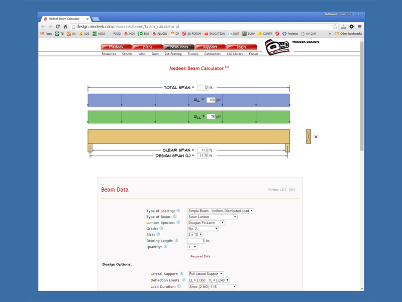
I've done some maintenance on the beam calculator in preparation for integration with the Truss Plugin:
Version 1.0.1 - 01.10.2016
- Updated javascript front end so that selected options are properly retained.
- Updated total load (reactions) to include applied load and selfweight over total span. Results now more closely agree with WoodWorks Sizer Software.
- Inputs now include option for Total Span and Clear Span.
- Removed beam configurations that are not yet complete.
- Beam graphic now shows span geometry with supports.
At some point I need to come up with a slicker interface that allows for multiple point loads and supports but that is a job for another day.
-
Version 1.2.5 - 01.10.2016
- Plugin integrated with the Medeek Beam Calculator.
- Engineering of North American glulam beam sizes enabled (Western, Southern Pine).
Also note that the Beam Calculator has a very nice PDF report output than can include client and job information.
-
Screenshot of the Beam Calculator that will pop up when called from the plugin:

So far I only have glulam beams as an option in the plugin but I will probably add LVL, LSL, PSL and Solid Sawn and those can also be analyzed with this same interface.
-
Is the manual a WIP?
-
My wife is helping with the manual. I'm also going to make a few tutorial videos per some requests from other users. I think at this point the plugin is complicated enough it warrants more complete documentation.
-
First tutorial video:
-
Watched the video. Good job! Quite clear and nice to watch.
-
@medeek said:
First tutorial video:
thank you for the video
i remember the difficult part, when i was designing wooden structures, was the connections between the members...
designing the connections might be a useful feature
i am longing to see a video about how you use the parameters in the dynamic component dialog box, as an input for your web calculator...
-
IFC Classifications
I do not see IFC definitions of the truss components.
Will this be included in future versions of your plugin/extension?T2H BuildingStructureTools (by Tak2hata) is a good example of the implementation
of SketchUps IFC Classifications.Keep up the good work - I learn a little more about Trusses
with each or your new posts
-
I have not even looked into the IFC classifications yet. At this point I'm not even sure how to classify a truss with that classification system. I will look into that further.
-
Engineering Video:
The SketchUp model used in the video can be found here:
3D Warehouse
3D Warehouse is a website of searchable, pre-made 3D models that works seamlessly with SketchUp.
(3dwarehouse.sketchup.com)
All of my sample models can be found here:
3D Warehouse
3D Warehouse is a website of searchable, pre-made 3D models that works seamlessly with SketchUp.
(3dwarehouse.sketchup.com)
-
Valley Truss Set:
-
Hip Roof Framing:
SketchUp model used in the video can be found here:
3D Warehouse
3D Warehouse is a website of searchable, pre-made 3D models that works seamlessly with SketchUp.
(3dwarehouse.sketchup.com)
-
Somewhat of an aside for other plugin developers or those using the API to create geometry:
I found with the compound miter cuts required for the hip roof framing that the easiest way to handle this was by doing a push pull to the correct length so that one side of the member was the correct length and then actually selecting an edge or vertex and moving this separately to create the angles required. In some cases this can get a little messy since it may introduce extra lines that bisect a plane but some simple logic can then delete those extraneous lines after the fact. I don't know if this is the most efficient method to do this sort of thing but after some testing I managed to get it work very reliably.
-
@pbacot said:
Watched the video. Good job! Quite clear and nice to watch.
My wife says I need to stop clearing my throat as I talk, other than that I think they mostly get the point across.
I'm still working on the manual, I've been busy the last few days so progress is slow. I've been looking around at other plugins the last few days and I'm beginning to wonder if my price point on this might be too high, most plugins are either free or a few dollars. Feedback in this regard is very much appreciated. I don't intend on making a lot of money on this project but I feel that I should at the same time be fairly compensated for the time and effort I have devoted.
-
You could always take one of the early versions of the plugin, with limited functionality (limited to say a certain type / types of trusses and possibly limited spans) and release it as a free version (probably without support, else you'll be inundated with queries), this is to wet people's appetite and to get them to use the plugin and buy into the paid version (with full and expanded functionality). You already have the full version going (rename to pro?), then there's a third tier (engineering version?) possibly as per the PM I've sent you.
-
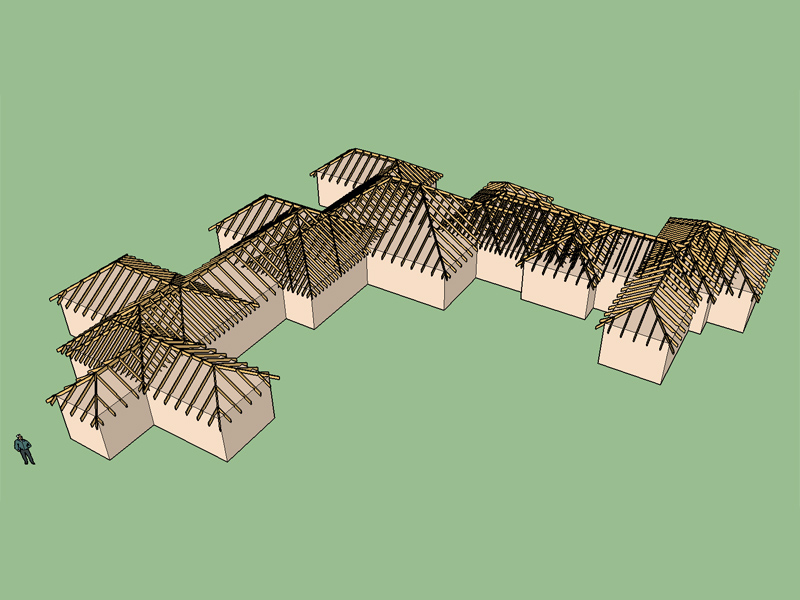
Testing the limits of the Medeek Truss Plugin with complex hip roofs. Note that the roof primitives have not been trimmed back. This is primarily a study to determine what additional programming would be required to generate this type of roof automatically:

This for me would be the holy grail of hip roof framing...
3D Warehouse
3D Warehouse is a website of searchable, pre-made 3D models that works seamlessly with SketchUp.
(3dwarehouse.sketchup.com)
-
As you can see there is still a tremendous amount of work that can be done here. To that end I've started a KickStarter project which if successful would allow me to devote at least 4-5 months of my undivided attention on the programming of this plugin:
-
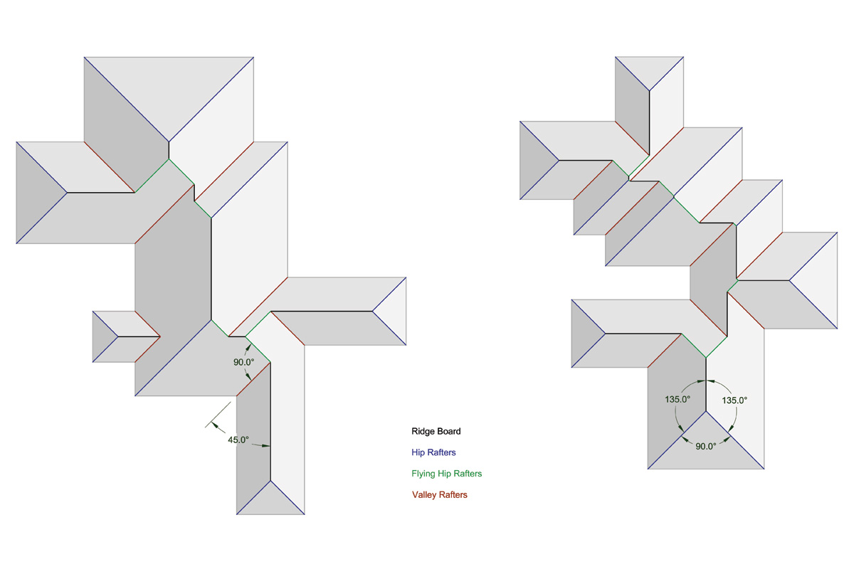
Pondering complex hip roofs this afternoon and considering the graphic below:

A few rules seem to emerge:
1.) An outside corner will always create a hip that is 45 deg. from each leg of the corner.
2.) An inside corner will likewise always create a valley 135 deg. from each leg of the corner.
3.) Where two hips or flying hips meet a ridge will extend 135 deg. from each hip.
4.) When two valleys meet at 90 deg. they will terminate and a ridge will extend at 45 deg. from each valley.
5.) With a building with walls only running north-south or east-west all ridge lines will always be north-south or east-west.
6.) Likewise all hips, valleys and flying hips will be oriented northwest, northeast, southwest, or southeast.
7.) When a valley meets a ridge, (they will always meet at 45 deg) a flying hip is generated that is 90 deg. from the valley and 135 deg from the ridge.
8.) When two valleys meet at 180 deg. from each other, the result will be either to flying hips perp. to the valleys or the degenerate case of 4 valleys and 4 ridges.
9.) When a valley and a hip meet each other at 180 deg. then two ridges that are 45 deg from the valley will be the result (typical L shaped roof).
10.) When 4 hips meet the result is a pyramid.There may be a few other degenerate cases I'm missing but I think that covers it.
Advertisement


