3D Truss Models
-
***** CHRISTMAS SPECIAL *****
This year after Thanksgiving we ran a Cyber Monday special (SketchUcation Newsletter) on just the Wall Plugin and the reception was excellent. Unfortunately, I did not run the Truss Plugin with that same promotion. In lieu of a Thanksgiving promotion I will be running a 24 hour Christmas Special instead for the Truss Plugin.
The special will only run from 12:00AM - 11:59PM (PST) on December 12th, which is tomorrow. The price will be marked down to $35.00 (USD). You do not need a discount code, when you go to purchase the price will come up as the discounted price above. This discount only applies to new purchases and not to renewals.
Once the special has ended I will not be accepting requests to honor the special at a later date, there will be no "rain checks".
Thank-you for your support and a very Merry Christmas to all and prosperous New Year.

-
Should anyone be this deep into this thread and not have realized how useful this extension is, take my word for it, it is very useful. If you're sitting on the fence the one-day once-off Christmas discount being offered is plenty of incentive to get it.
-
Version 2.2.5 - 12.08.2018
- Added Trim 2 icon to the Medeek Tools toolbar.
- Added the trim 2 function for (solid) groups and components. This trim function allows the user to select two trimming planes.
This additional trim function will be helpful in trimming more complicated geometry like hip rafters and triangular pieces of roof sheathing or cladding.
Similar to the regular trim function this tool can also be utilized on any non-plugin geometry so long as it is a (solid) group or component.
View video here:
-
In order to round out the selection of tools available and also per suggestion from a respected colleague it would seem prudent that I also include a mitering tool in the grab bag that is the Medeek Tools.
This can take shape in a few forms however the most important configuration in my opinion would be a tool that can take two solids and miter both of their ends at a common plane, while retaining the solid status of the group or component and retaining all of their properties and meta-data.
This would involve selecting the faces to extend/trim on each solid and then selecting two (non-parallel) edges that intersect at a point, so four pick points in total. The intersecting edges need not be orthogonal (90 degrees) just so long as they intersect at a point, that is enough to define the mitering plane.
I haven't searched very much yet to see if such a tool/plugin already exists and I don't really want to recreate the wheel on this one. Please let me know if you are aware of such a tool, that can work for any (non-plugin specific) solids.
Would there be a need/demand for this proposed tool?
-
Seems Profile builder has such tool page 28-31...?
-
-
Not specially it's for repare one by one if miter joint of an existing object(page 35) is not as you want...
-
Version 2.2.6 - 12.16.2018
- Added the Miter Cut icon to the Medeek Tools toolbar.
- Added the Miter Cut function for (solid) groups and components.
- Enabled temporary (construction) dimensions for trusses, roofs and floor assemblies.
- Added a section in the General tab of the global settings for configuring construction dimensions.
Tutorial 12 - Miter Cut:
-
Version 2.2.5c - 12.13.2018
- Added the Trim 3 icon to the Medeek Tools toolbar.
- Added the Trim 3 function for (solid) groups and components. This trim function allows the user to select three trimming planes.
- Enabled the ability to invert your selection within the Trim 2 and Trim 3 tools using the "CTRL" key in Windows.
Tutorial 11:
Note that the planes in either advanced trim tool do not need to be orthogonal.
When using the Trim 3 tool the suggested order of selecting the cutting planes/faces is:
Vertical - Vertical - Horizontal
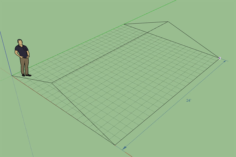
On an outside corner like that I'm not entirely sure how a skilled roof framer would cut that birdsmouth, but at least with the Trim 3 tool you have the option to cut it so it fits tight to the wall as I've shown in the video.
I like including this toolset as part of the Truss plugin, but I am also wondering if there might be a potential market for it as a stand alone plugin ($5 - $10). As it stands currently the prospective user is forced to purchase the entire Truss Plugin if they want to use these tools.
-
I'm a little burned out right now with the addition of all these extra tools to the Medeek Tools toolbar, but I still feel like I need to add one final addition to the mix.
This one will be called the split tool and similar to the trim tool the user will select a single face (or three points, toggle with the control key?) to define a plane which will then be used to cut a solid group or component in two.
The slightly tricky part with this is to make sure that the copied group/component is nested in the same overall group(s) as the original and retains all of its properties.
This tool would be useful where you've used the followme tool to create some geometry but want to break the resulting solid into separate segments (groups).
-
Seems a very colol "knife"!

-
Version 2.2.6b - 12.18.2018
- Added the Split icon to the Medeek Tools toolbar.
- Added the Split function for (solid) groups and components: split plane via one face or three points.
When you first click on the tool it defaults to the user selecting a face for the cutting plane however if you hit the "CTRL" key in Windows it will toggle to the three point mode.
Tutorial 13 - Split Tool:
-
Version 2.2.6c - 12.18.2018
- Addressed a bug in the Split function regarding nested groups and components.
This is a critical fix for this tool. I strongly suggest that everyone upgrade from 2.2.6b to 2.2.6c.
Let me know if there are any other tools that might come in handy with manipulating an architectural model. I think the six tools now available can cover most tasks but I'm sure I'm missing something.
-
There has been some call for a tool that is similar to the split tool but rather than selecting just one face you would select two faces and a section could be removed from the solid object (imagine two infinite planes cutting a slice out of your solid object). I'm not exactly sure what to call this possible tool (section cut?).
The other question is whether to have the tool break the solid into two separate groups or components like the split tool or just leave the resulting geometry as one group/component? I suppose I could always enable an option that would allow the user to toggle between these to behaviors offering some flexibility to the user.
Similar to the split tool I could allow the user to define the cutting planes but either selecting two faces or selecting six points, or a combination of three points and a face or a face and three points. Lots of permutations here... just makes the code a little more fun.
With regards to the cutting planes, they could be parallel or they might not be, it doesn't really matter. Just as I am doing in the split tool I will need to include logic that checks to see that the cutting planes actually do intersect the solids otherwise no action will be performed. The two cutting planes cannot be perpendicular to each otherwise a valid solution cannot be obtained, or at least that is what I initially thought. I will need to give that possible solution some more thought. If a solution can be obtained there is no reason to discard it. There may be some overlap with the Trim 2 function, but that tool does not have the ability to separate the solid into different groups.
Any thoughts or suggestions with regard to this potential addition to the tools?
Also just a reminder that even though I am including these tools within the Truss plugin they are designed to work with any solid geometry created in SketchUp, it doesn't need to be plugin related geometry.designed to work with any solid geometry created in SketchUp, it doesn't need to be plugin related geometry.
-
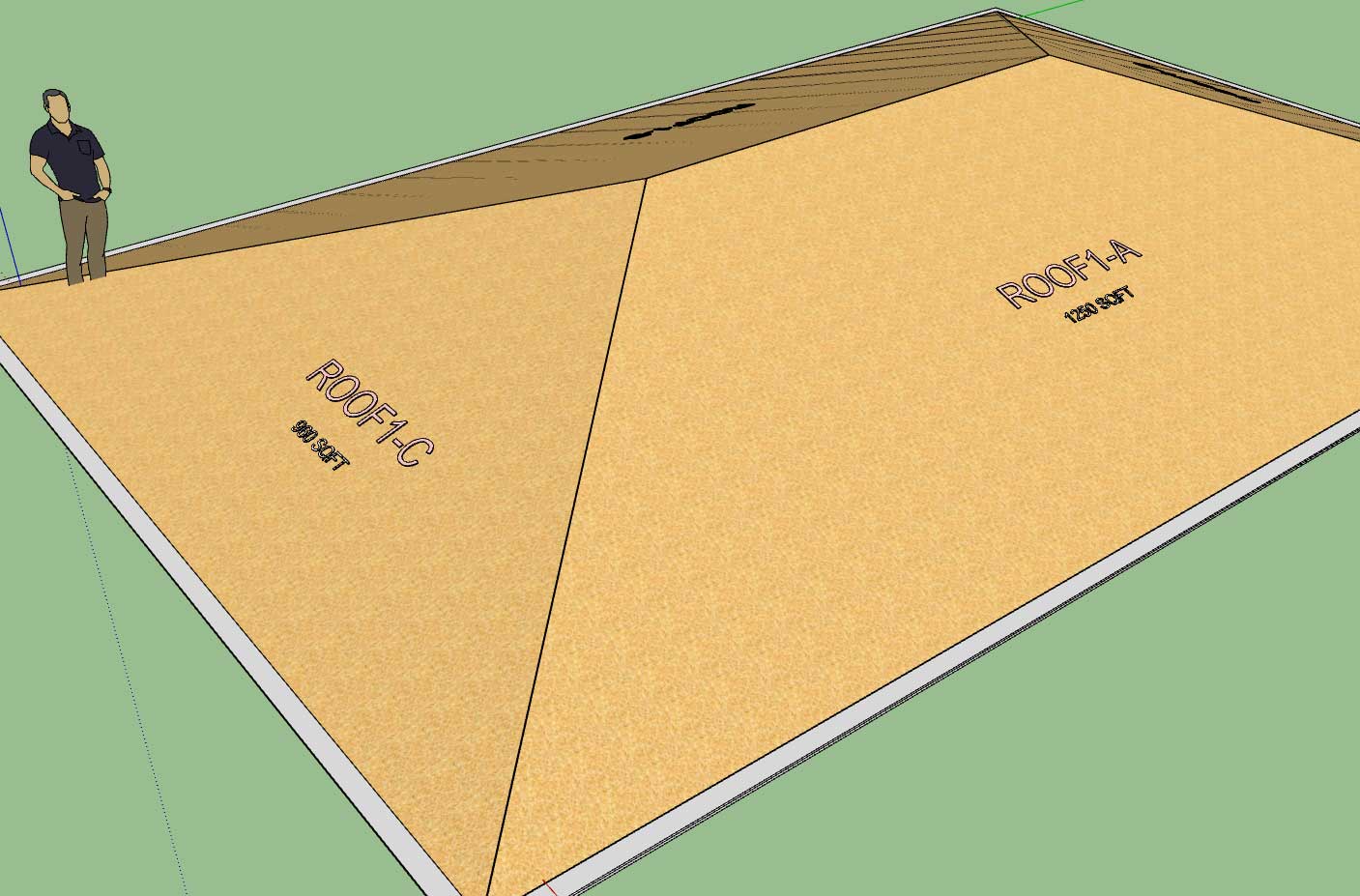
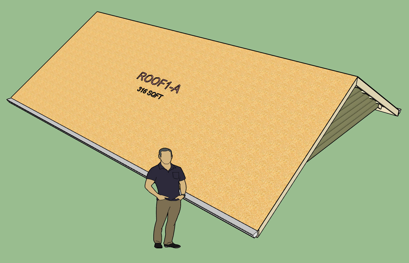
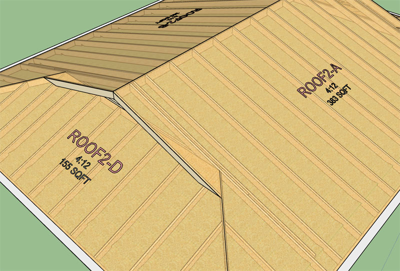
I've been thinking about labels for truss and rafter roofs and I would like to add in some sort of labeling system like the Wall plugin.
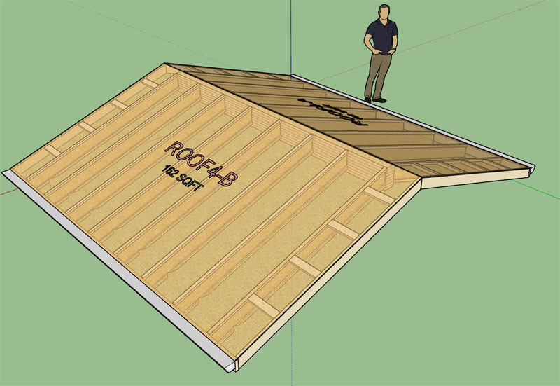
With a typical gable roof I will have a label on each side of the roof aligned with the roof plane but offset vertically so it does not Z fight with the sheathing or cladding (shingles). The label will be similar to the Wall plugin where the user can customize the prefix (eg Roof1, Truss1, Rafter1 etc...)
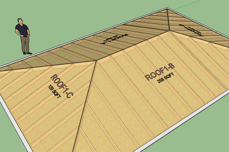
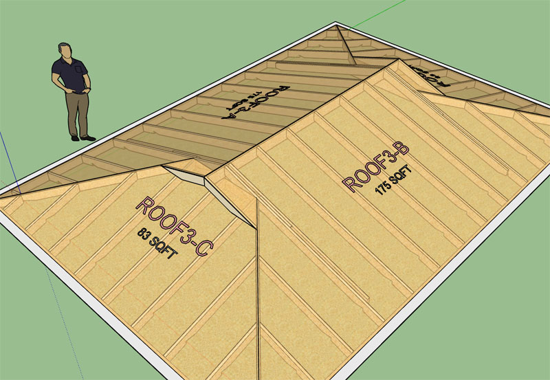
Each side will be designated a letter, so Roof1-A and Roof1-B. Hip roofs will have four roof planes so A, B, C and D.
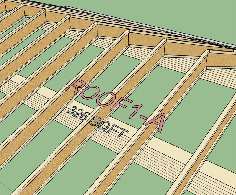
If the framing callout is enabled then beneath the label will show the area for that roof plane (sheathing):
-
Version 2.2.7 - 12.27.2018
- Roof and Floor labels option added to the General tab of the Global Settings.
- Roof and Floor label prefixes can be customized in the General tab of the Global Settings.
- Roof labels enabled for common trusses.
- When framing callouts are enabled the area of each roof plane will be shown below the roof label (currently only common truss assemblies have this feature available).
- Added a customizable color for roof and floor labels within the Material tab of the Global Settings.
- Added additional layers for dimensions, annotations, 2d geometry, building code and engineering.
-
Version 2.2.7b - 12.29.2018
- Enabled roof labels and framing callouts for monopitch truss assemblies.
- Added stats (roof sheathing) for common and monopitch truss roofs which can be analyzed within the Medeek Estimator (Wall Extension) module.
In order to use this new feature you must also have the Wall plugin installed and upgraded to Version 0.9.9v, See Wall plugin thread for further details.
-
Version 2.2.7c - 12.30.2018
- Enabled roof labels and framing callouts for all rafter roof assemblies: Gable, Hip, Dutch Gable, TJI, TJI w/ Glulam, Shed etc...
I've also been thinking about how to best handle holes or cutouts in the roof sheathing and cladding that are not only parametric but can be properly reported by the estimator (ie. net area vs. gross area). I think I have a system worked out, I just need to implement the prototype and test it out.
The cut out or hole tool will have a few options. One of the options will allow the user to specify whether to cut the cladding, sheathing or framing or all of them. If the framing is cut then another option for framing in the opening.
I may also provide another option to provide a skylight to cover an opening or other construction elements (eg. vents, whirlybirds etc...)
-
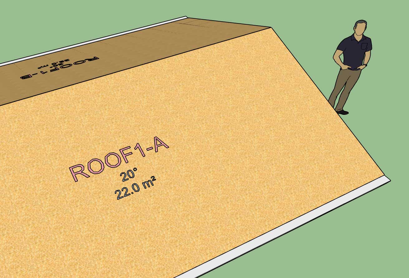
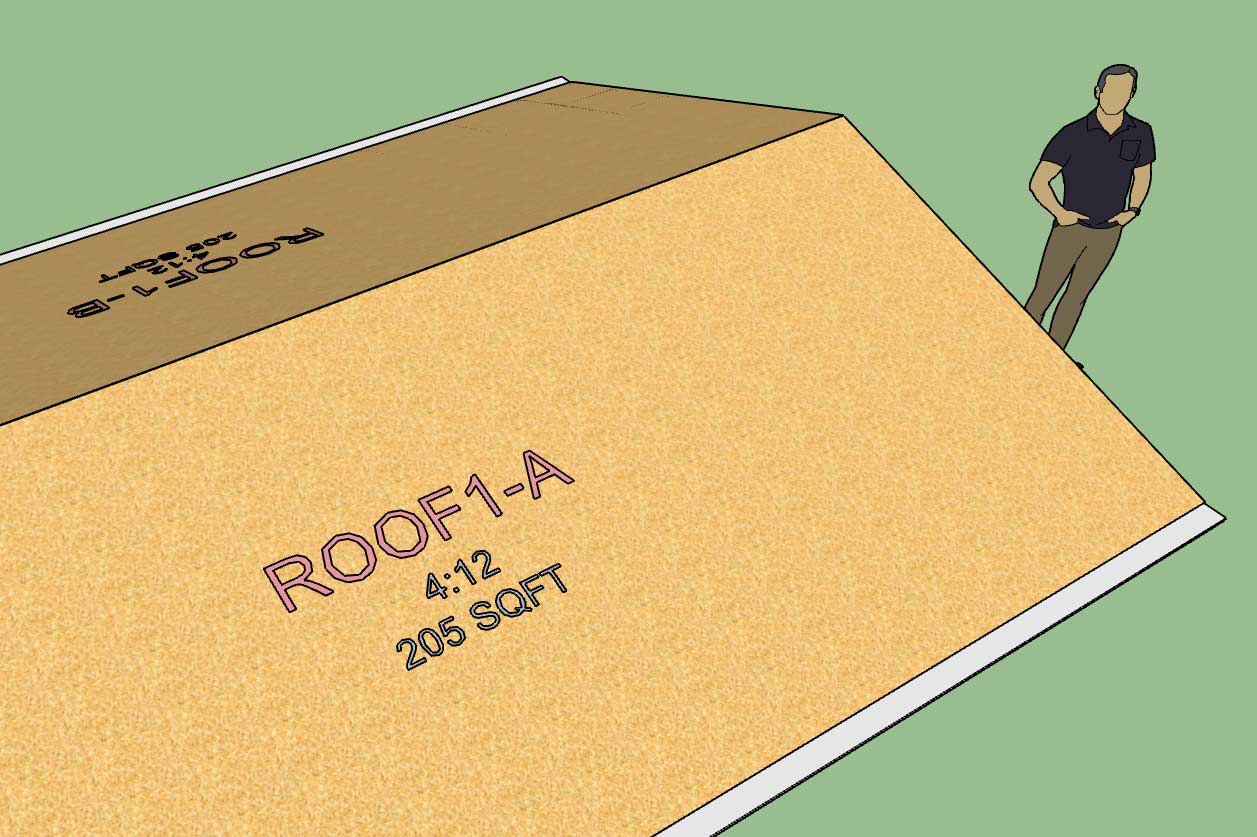
Another basic piece of information of any roof is the pitch or angle in degrees for the metric side of the house. I'm updating the framing callout for roofs to also include this information:
-
Version 2.2.7d - 01.04.2019
- All roof framing callouts now include the roof pitch or angle in degrees (metric templates).
- Added additional stats: (ridge cap, drip edge) for common and (drip edge) for monopitch truss roofs which can be analyzed within the Medeek Estimator (Wall Extension) module.
The new stats will become available with the next release of the Wall plugin.
Hello! It looks like you're interested in this conversation, but you don't have an account yet.
Getting fed up of having to scroll through the same posts each visit? When you register for an account, you'll always come back to exactly where you were before, and choose to be notified of new replies (either via email, or push notification). You'll also be able to save bookmarks and upvote posts to show your appreciation to other community members.
With your input, this post could be even better 💗
Register Login


Advertisement