3D Truss Models
-
The birds mouth cut algorithm (and code) is now functional however I can't say I'm completely satisfied with it yet.
For example take a look at this scenario:
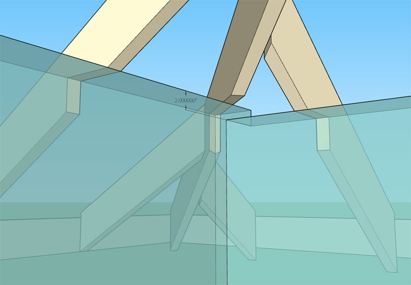
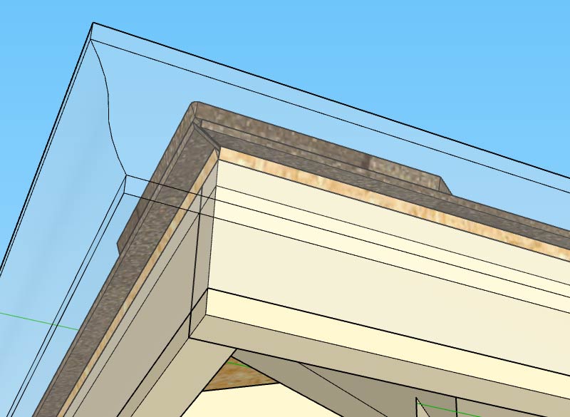
You have a 8:12 and 7:12 meeting almost at the corner of the building (skew is minimal) however the plate height is 2" higher on the 7:12 side and my algorithm cuts the birds mouth per the highest plate height at the corner.
In this particular case it would seem to make more sense to cut the birds mouth at the lower plate height otherwise not enough meat is left in the hip rafter. This algorithm may need further refinement to really make it meaningful and useful to the designer.
The other option of course is to simply not cut the birds mouth in the hips rafters and leave it to the user to determine what or how they want to handle the intersection at this critical junction.
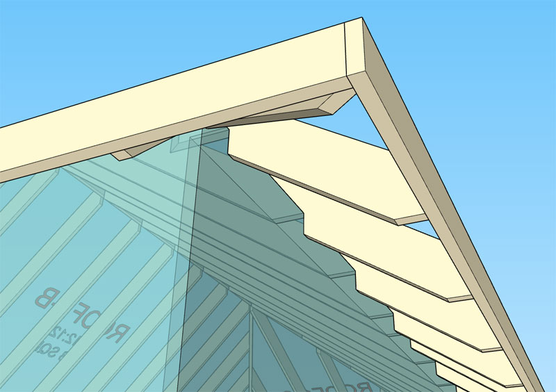
The soffit cut in the case of a hip roof is actually quite simple (surprisingly). Since the fascia lines up all the way around the roof the soffit cut will also be the same height for all jacks, commons and hip rafters.
-
The soffit cut function is now active for hips, jacks and commons:
Now I will see if I can break the module, I'm sure there is some state or configuration that I haven't considered that may throw some errors.
-
Version 2.3.7 - 05.13.2019
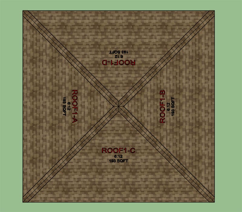
- Enabled asymmetric hip rafter roofs (imperial and metric units).
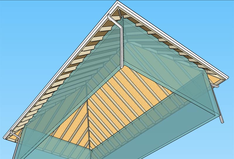
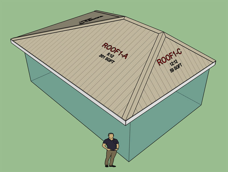
The most degenerate version of the asymmetric hip roof would be a pyramid roof. The roof shown below is a pyramid roof that is actually an asymmetric roof, as you can see the algorithms degenerate gracefully as they should:
Items for future work include the ability to toggle the configuration where the sheathing centers up on the ridge board or not.
Another outstanding item is ceiling joists. I'm not even sure what do with ceiling joists yet for an asymmetric hip as there could possibly be four different ceiling joist heights.
I would also like to switch everything to HTML menus. The initial draw menu is still using the default SU GUI. Due to its limitations you can only initially create symmetric hip roofs but then you can edit them to switch them to an asymmetric configuration. I will explain this further in an upcoming tutorial video. Once I switch to an HTML draw menu this limitation will be resolved.
-
Download or view a sample of an asymmetric hip roof here:

3D Warehouse
3D Warehouse is a website of searchable, pre-made 3D models that works seamlessly with SketchUp.
(3dwarehouse.sketchup.com)
-
I've fixed a few small bugs with the jack rafters near the corners and re-released the plugin.
When the jack rafters approaches a corner and then the overhang portion of the roof the various permutations in the way the jack rafter is beveled or cut becomes quite interesting. With a regular symmetric hip roof the possible configurations is more limited and predictable however the asymmetry lends itself to additional cases, so more conditionals are required in the code to account for them.
I've ran some additional checks to try and ferret out these additional configurations and then provide the appropriate logic to handle them, however there may still be a few that may have eluded my best efforts. This module is new so there may still be a few fires yet.
-
Tutorial 15 - Asymmetric Hip Roofs:
In this video I try to explain how each roof plane can be adjusted and the details of toggling between auto calculating the overhang or the top plate height.
View model here:
3D Warehouse
3D Warehouse is a website of searchable, pre-made 3D models that works seamlessly with SketchUp.
(3dwarehouse.sketchup.com)
Looking at hip roof again this afternoon it occurred to me that it probably would be useful to have the ability to specify the depth of each hip rafter individually and for a symmetric roof the ability to specify the hip rafter depth independent of the common rafter depth. Yet another item to add to this modules todo list.
I also need to update the estimating module for this roof type (symmetric and asymmetric), the quantity and length of each jack rafter would be useful information.
-
Giving some thought to the secondary roof tool:
-
Trying to come up with an intuitive method for specifying a secondary roof. My idea is for the user to select the wall corners (1) and (2) that the projecting (secondary) roof will be bearing on and then to select the roof plane of the primary roof that the secondary roof should intersect. Essentially three points/picks will specify the secondary roof.
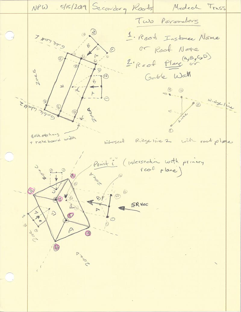
When a secondary is created it will store the primary roof name it is intersecting with as well as the roof plane. Either of these can then be modified in the secondary roof menu in the case that the user wants to switch to a different primary roof or a different roof plane of a given primary roof.
When a secondary roof is edited or regenerated it will then re-analyze the entire geometry with the specified primary roof and roof plane in order to generate the secondary roof geometry. This will allow the user maximum flexibility (ie. moving primary and secondary relative to each other {x, y, or in z} as well as changing the primary).
Orthogonal intersections are nice but we can't count on them so from the get go the secondary tool will be designed with any arbitrary intersection angle in mind as well as intersections with a roof planes or gable ends of a gable roof (wall).
Additionally, the secondary roof may be symmetric or asymmetric so it makes sense to also allow for this possibility as well.
One could even go so far as to allow for intersection with more exotic primary roofs (eg. gambrel, arched, polynesian etc...) however at this point I think I will limit myself to just a single pitched roof plane or wall plane.
There will be a separate tool for secondary hips and one for secondary gables, the reason being the vast number of different parameters required for each type of roof and the different algorithms required as far as calculating the actual roof rafter geometry.
At this point I am mostly conceptualizing and trying to see if there are any major holes or flaws in this system or method of secondary roofs. I would be interested to hear your feedback on the matter and especially if you can see any major problems with my methodology, or have suggestions for something that may work even better.
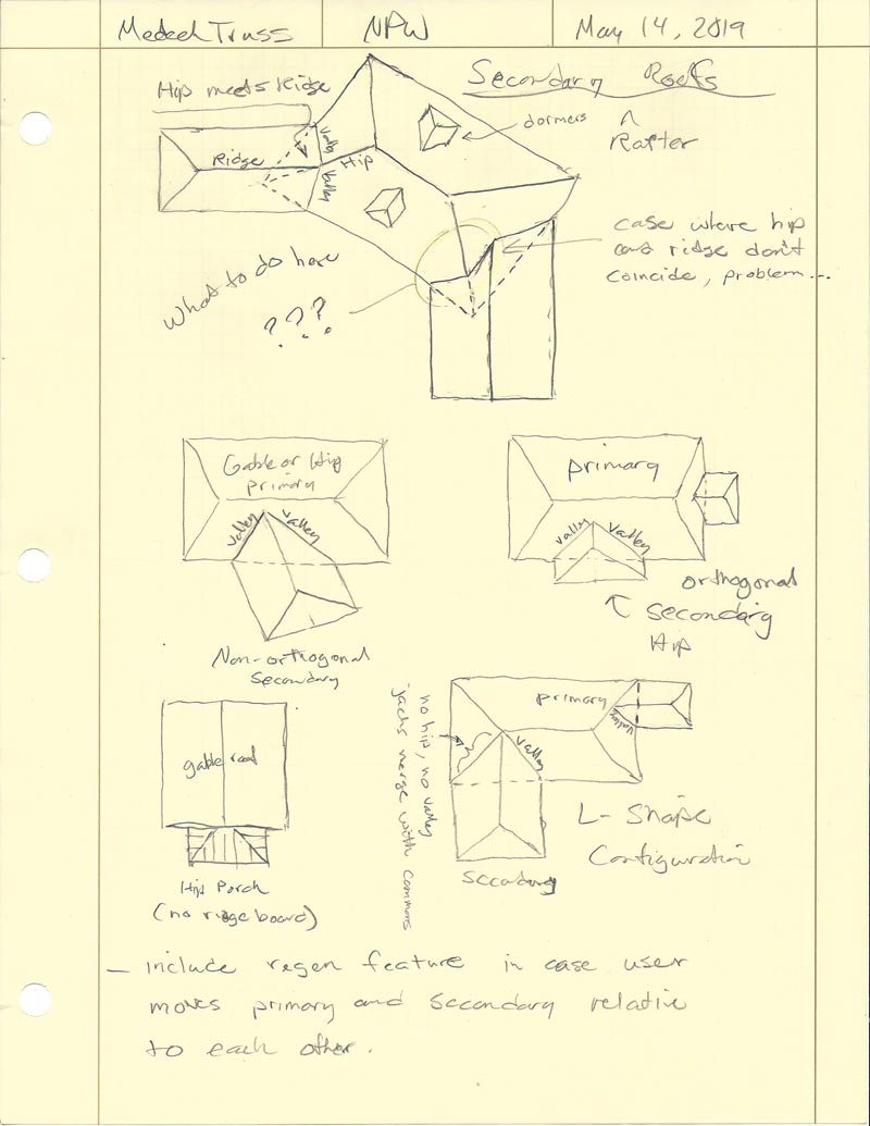
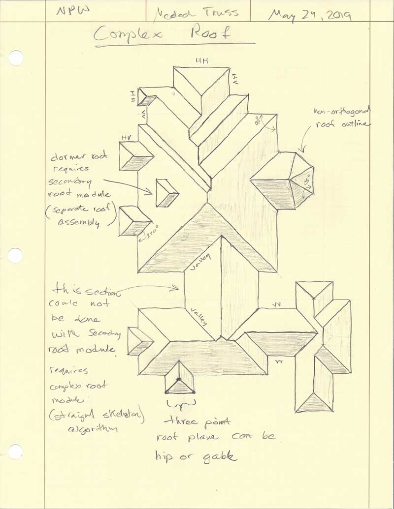
As can be seen on my previous notes page (May 14), there are a few special cases that will also need to be dealt with:
1.) Secondary roof is non-orthogonal to the primary roof and its ridge coincides or meets a primary hip. In this case the secondary really should intersect the two planes on each side of the primary's hip.
2.) A hip roof secondary meets a gable wall such that the aspect ratio of the secondary precludes it from having a ridge board perpendicular to the gable wall. There is also potentially the non-orthogonal possibility but this would not be very common.
3.) Typical L-shaped hip roof where the valley and hip theoretically merge into a common roof.
If I can somehow pull this one off, it will be a bit of a game changer for the Truss plugin since it will then allow for much more complicated rafter roofs.
-
Before I fully dive into the secondary roof module I thought it might be interesting to return to the soffit and fascia discussion I was having back in 2017. It would be nice to have soffit and fascia added to the hip rafter roof modules.
However as I am reviewing my notes and previous posts I came upon one unresolved question.
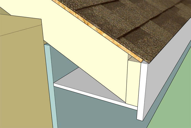
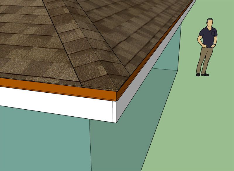
Should the roof sheathing extend out over the fascia board or should it terminate at the sub-fascia as shown in this detail:
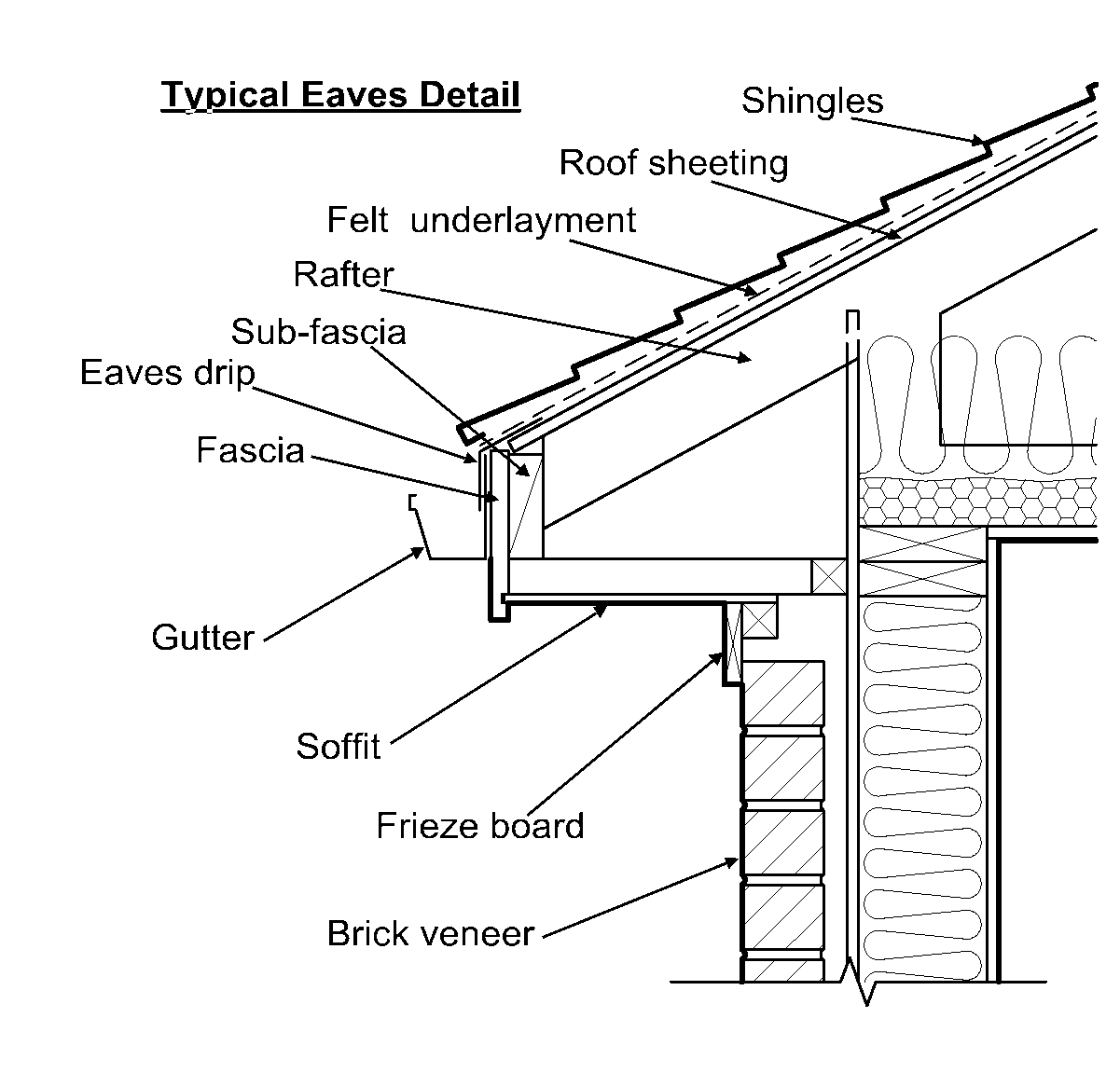
The reason this becomes an issue is that the calculations of an asymmetric hip roof factor in the width of the sub-fascia in order to line them up around the roof. If the sheathing extends pasts the sub-fascia to the fascia then the gutter line will drop a different amount for each roof plane depending on the pitch. However if the sheathing only extends to the extent of the sub-fascia then the calculations for the roof do not need to take into account fascia width.
I can have it work either way but I would like to focus on the most common configuration.
-
Version 2.3.8 - 05.16.2019
- Fixed a bug with the pitch and area callouts for asymmetric gable rafter roofs.
- Fixed a bug with the back/rear outlooker length for gable rafter roofs which now allows for a building or roof length that is a non-integer multiple of the rafter spacing.
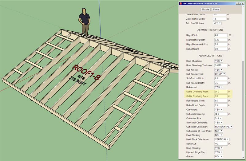
- Added the option in the gable rafter roof edit menu to specify a separate front and back overhang length.
The issue with the rear outlooker length will also need to be addressed for truss assemblies.
I should also make the option for the separate front and back overhang length available for trusses as well. Lots of little things as well as big things to do.
The consensus seems to be that the sheathing should terminate at the sub-fascia and not extend over the fascia, especially if the rafter tail is a plumb cut (fascia is vertical). However, this preference also seems to be highly dependent on the particular application and type of fascia used.
Here is another interesting detail:

-
A few other things to note with regards to fascia and soffit:
1.) In order to enable soffit and fascia the advanced options must be turned on and the sub-fascia option must also be turned on.
2.) The consensus appears to put the fascia top flush with the sub-fascia top with the sheathing terminating at the outside edge of the sub-fascia.
3.) Gutter placement will then be unaffected by the fascia other than be offset by its thickness.
4.) The soffit will be placed level to the horizontal and extend to the outside edge of the sub-fascia meeting the fascia and to the wall sheathing. Since the plugin is not keeping track of what walls are being used (Medeek, Framer, or a simple solid), there will be a wall sheathing offset parameter that will allow the user to control this offset. I've noticed some details showing the soffit extending to the framing, others to the sheathing and still others to a brick or stucco layer.
5.) The soffit top surface will abut the underside of the sub-fascia.
6.) Materials for soffit and fascia will both be user driven/customizable.
7.) Parameters to include: Soffit thickness, Fascia thickness, Fascia depth.
8.) I will also be adding in an additional parameter for the roof cladding which allows the user to extend it beyond the sheathing a specified amount (Roof Cladding Extension). This will naturally extend the ridge or hip caps the appropriate amounts as well.
I realize there are other soffit variations but I will be starting with the flat soffit first and then consider the angled soffit in future developments.
-
Version 2.3.9 - 05.17.2019
- Enabled a roof cladding extension parameter for all hip rafter roofs.
The extension is measured inline with the roof plane (not with the horizontal).
-
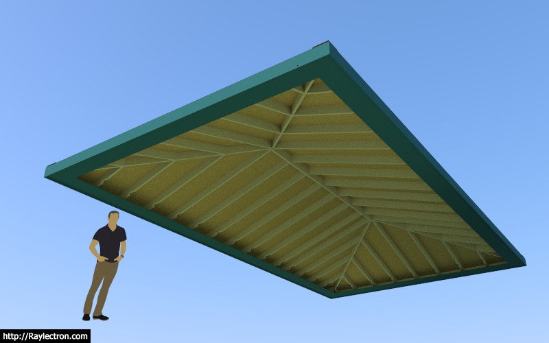
First look at the soffit and fascia (hip roof):
Also note the roof cladding extension (3/4") with a 6:12 pitch.
-
Version 2.4.0 - 05.19.2019
- Enabled soffit and fascia for all hip rafter roofs.
- Fixed a minor bug with the ridge cap extension for asymmetric hip roofs.
- Enabled custom materials for roof sheathing and roof cladding in the HTML edit menu for all hip rafter roofs.
Custom materials is also enabled for both the soffit and the fascia. Soffit and fascia can only be specified in the edit menu once the roof is created. The current draw menu presents the user with far less parameters and will be updated to a more advanced HTML menu in the future.
Once I am satisfied with the soffit and fascia with the hip roofs I can then extend it to gable, shed and dutch gable roofs and all other truss roofs.
View example model here:
3D Warehouse
3D Warehouse is a website of searchable, pre-made 3D models that works seamlessly with SketchUp.
(3dwarehouse.sketchup.com)
-
I'm considering adding in drip edge but then again it may be a step too far?
If gutter is enabled then the drip edge is barely visible. For estimating purposes I can just calc the perimeter of the roof to get the lineal feet of drip edge. Is it worth the effort?
-
After some further testing of the roof cladding extension parameter I think it makes more sense to make the extension per the horizontal and not per the roof plane. The problems really only seem to arise when you have an asymmetric roof, in this case the higher pitched roof will project less than the lower pitched roof if the extension is parallel to the roof plane.
Thoughts?
-
The two most common drip edges I've seen applied to residential roofs are the right two profiles shown in this image:
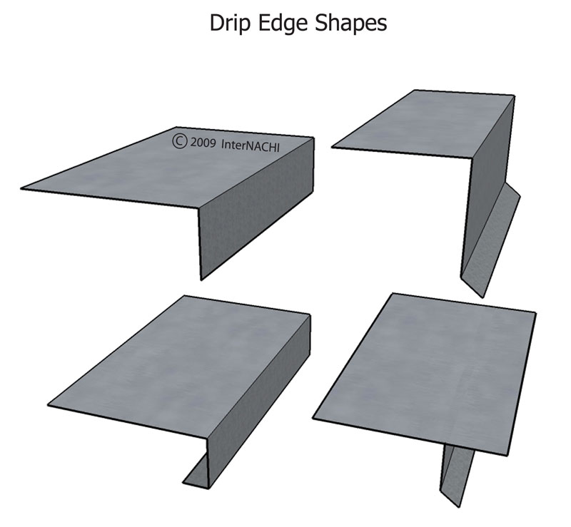
It would be more light weight to represent these metals as simple edges and faces but then they would Z fight with whatever they are resting on so I guess it is probably better to assign a thickness and model them as a solid instead.
So the two options to start will be a L or a D drip edge (not sure why they call it a D). The dimensions will all be customizable like the roof gutters.
-
I've decided to put the drip edge on hold for just a bit and focus on the secondary roof module.
There is really two ways to handle this. You can either start with a primary roof and then add secondary roofs that tie into it. Or you can allow the user to pick the building outline (any polygon) and utilize a straight skeleton algorithm to compute the roof planes. There are some pros and cons (limitations) to each method.
Obviously with the straight skeleton method one would assume that the fascia lines up all the way around the roof so it doesn't lend itself to secondary roofs like dormers that may be positioned up on the roof.
However, the straight skeleton allows for some really complicated scenarios that you just cannot achieve with a secondary roof methodology.
A few months ago I was trying to come up with a robust straight skeleton algorithm and somehow it defeated me. This morning I took a slightly different approach and I now think I've finally solved it:
Step 1:
Step 2:
Step 3:
Step 4:
Once I have the roof "solid" I can then easily pull out the edges that represent the hips, ridges, valleys and flying hips. From there it is just a matter of some tedious logic to detect whether to frame a common, hip jack, valley jack or cripple jack (hip/valley jack).
Of course the devil is in the details but I now think I have a path forward for complex roofs, this is major breakthrough.
-
I will also need a tool or function that allows the user to toggle specific roof planes from hip to gable or back again.
-
The complex roof algorithm seems to be fairly robust thus far, I haven't been able to break it just yet. However as I am contemplating how to make it so that each roof plane is adjustable (variable pitch) it is quickly becoming apparent that such a feature would become very complicated.
The issue really is a situation where you have a particular roof plane that you want to adjust. You then change its pitch (assuming all other pitches are left the same) and the roof gets recalculated. In certain situations that roof plane may then merge with another roof plane. If that happens then one of the two roof planes is absorbed by the other (both pitches must be equal of course).
The difficulty seems to arise in the tracking of each roof plane and the custom pitch assigned to it. The number of roof planes can be variable. The ability to edit each roof plane will need to be an "on the fly" sort of tool which allows the user to adjust only one roof plane at a time and then recalc the entire roof to re-determine the shape of the roof and hence how many and where its new roof planes actually are.
The easiest way to store this information, in my option. is to maintain the roof solid group (on a separate hidden layer). From this solid the roof planes can quickly be ascertained as well as the outline or footprint of the roof. I'm still thinking this one through as you can probably tell.
Initially the roof will be drawn with one overhang and one pitch. Where the edit menu can take it from there is where it potentially becomes quite complicated.
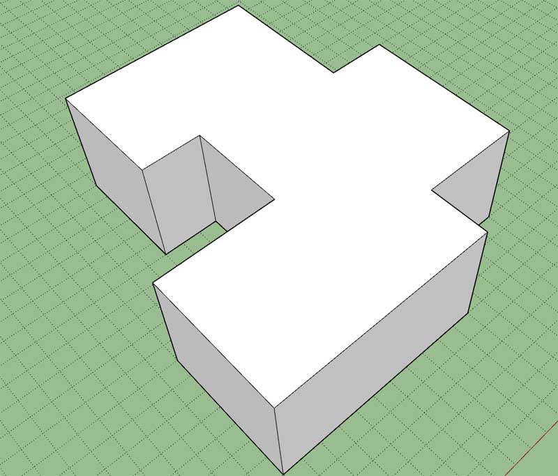
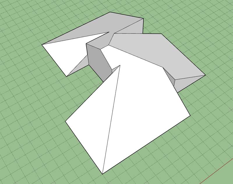
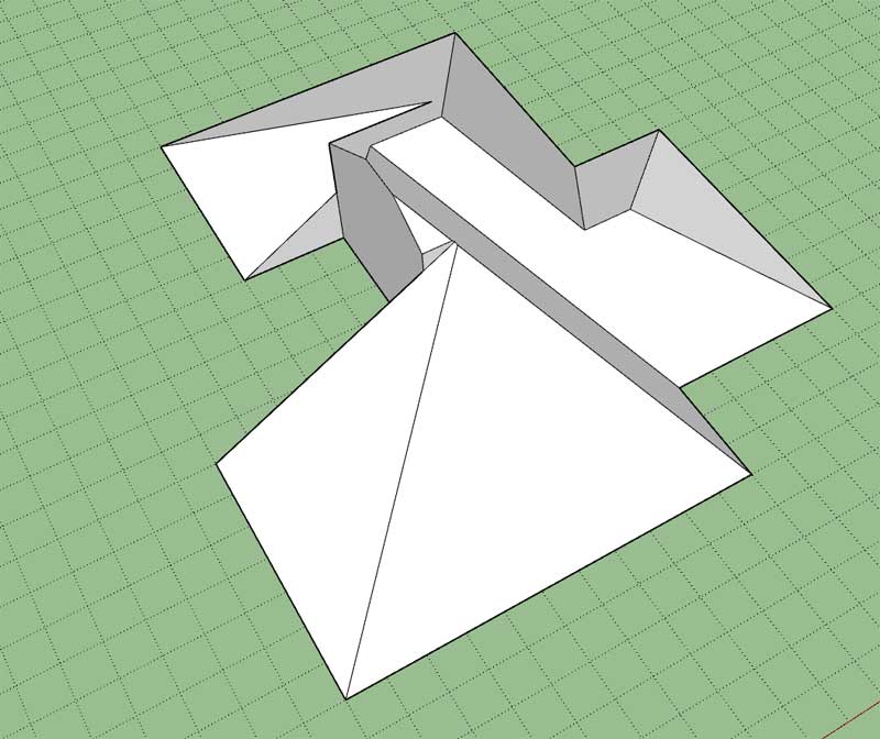
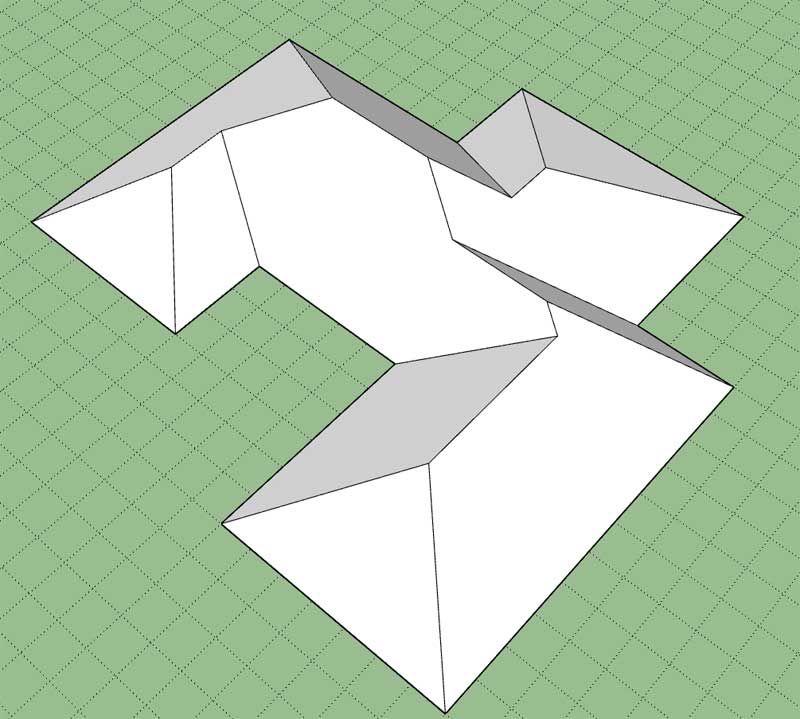
Consider a complex roof like the one below:
I can see that the framing can be accomplished with some basic rules/logic however non-orthogonal roof outlines will probably require some additional logic.
The tool that allows the user to define the footprint or outline of the roof should allow for the selection of a face or allow the user to pick points that then define the closed path of the roof outline. The code required to do this is already within my foundation plugin and will only need some minor modifications to make if work for this module as well.


Advertisement