3D Truss Models
-
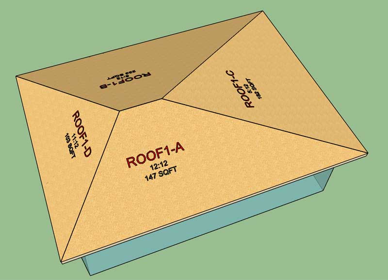
Pitch and SQFT callouts/labels are now working:
-
Hip and Ridge Cap is now working:
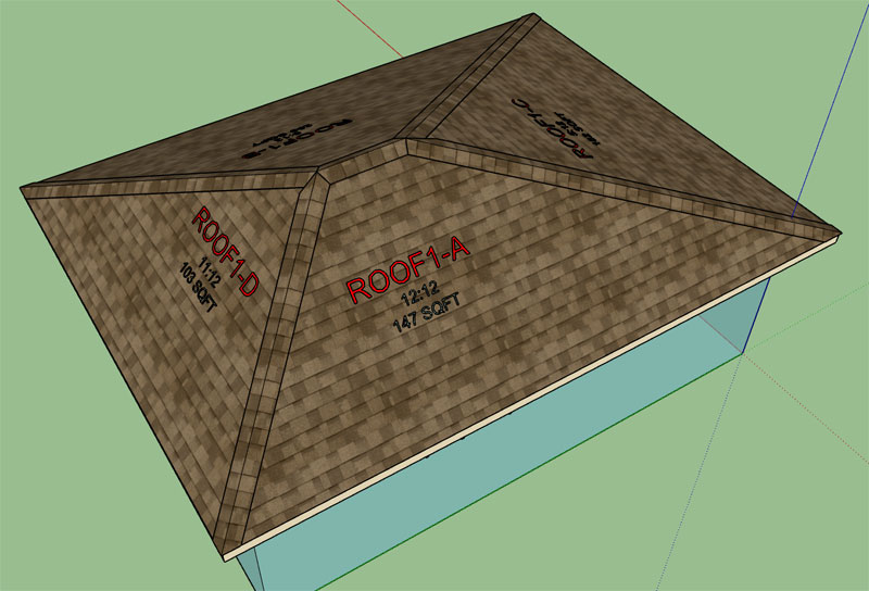
This chunk of code is just for the ridge cap geometry:
@Phi1_3 = atan(sin(@Phiplane13) * tan(@Phi) * cos(@Phihip13)) @Phi3_1 = atan(cos(@Phiplane13) * tan(@Phi3) * cos(@Phihip13)) @Phialpha1_3 = acos(cos(@Phihip13) * sin(@Phiplane13)) @Phialpha3_1 = acos(cos(@Phihip13) * cos(@Phiplane13)) @Psi1_3 = asin(0.70710678118 * sqrt(1.0 - cos(@Phi)*cos(@Phi3))) @Phi2_3 = atan(sin(@Phiplane23) * tan(@Phi2) * cos(@Phihip23)) @Phi3_2 = atan(cos(@Phiplane23) * tan(@Phi3) * cos(@Phihip23)) @Phialpha2_3 = acos(cos(@Phihip23) * sin(@Phiplane23)) @Phialpha3_2 = acos(cos(@Phihip23) * cos(@Phiplane23)) @Psi2_3 = asin(0.70710678118 * sqrt(1.0 - cos(@Phi2)*cos(@Phi3))) @Phi1_4 = atan(sin(@Phiplane14) * tan(@Phi) * cos(@Phihip14)) @Phi4_1 = atan(cos(@Phiplane14) * tan(@Phi4) * cos(@Phihip14)) @Phialpha1_4 = acos(cos(@Phihip14) * sin(@Phiplane14)) @Phialpha4_1 = acos(cos(@Phihip14) * cos(@Phiplane14)) @Psi1_4 = asin(0.70710678118 * sqrt(1.0 - cos(@Phi)*cos(@Phi4))) @Phi2_4 = atan(sin(@Phiplane24) * tan(@Phi2) * cos(@Phihip24)) @Phi4_2 = atan(cos(@Phiplane24) * tan(@Phi4) * cos(@Phihip24)) @Phialpha2_4 = acos(cos(@Phihip24) * sin(@Phiplane24)) @Phialpha4_2 = acos(cos(@Phihip24) * cos(@Phiplane24)) @Psi2_4 = asin(0.70710678118 * sqrt(1.0 - cos(@Phi2)*cos(@Phi4))) @Ridgex = (cos(@Phi)*@HRthk*tan((@Phi + @Phi2)*0.5)) - sin(@Phi) * @HRthk @Ridgey = (sin(@Phi)*@HRthk*tan((@Phi + @Phi2)*0.5)) + cos(@Phi) * @HRthk if @Sheathing_option == "YES" if @Roofbatten == "YES" if @Cboption == "YES" thtot = @Cbheight + @Battenheight + @Sheathing_thickness + @Roofcladding_thickness else thtot = @Battenheight + @Sheathing_thickness + @Roofcladding_thickness end else thtot = @Sheathing_thickness + @Roofcladding_thickness end else if @Roofbatten == "YES" if @Cboption == "YES" thtot = @Cbheight + @Battenheight + @Roofcladding_thickness else thtot = @Battenheight + @Roofcladding_thickness end else thtot = @Roofcladding_thickness end end # Extension at Peak @Wa3 = PI - (@Phialpha3_1 + @Phialpha3_2) @Beta23 = atan(sin(@Wa3)/(tan(@Psi1_3)/(tan(@Psi2_3)) + cos(@Wa3))) @Beta13 = @Wa3 - @Beta23 ext13 = (thtot * tan(@Psi1_3))/(tan(@Beta13)) ext23 = (thtot * tan(@Psi2_3))/(tan(@Beta23)) @Wa4 = PI - (@Phialpha4_1 + @Phialpha4_2) @Beta24 = atan(sin(@Wa4)/(tan(@Psi1_4)/(tan(@Psi2_4)) + cos(@Wa4))) @Beta14 = @Wa4 - @Beta24 ext14 = (thtot * tan(@Psi1_4))/(tan(@Beta14)) ext24 = (thtot * tan(@Psi2_4))/(tan(@Beta24)) # Ridge Length and Extensions ridgedx = (cos(@Phi)*thtot*tan((@Phi + @Phi2)*0.5)) ridgedy = (sin(@Phi)*thtot*tan((@Phi + @Phi2)*0.5)) length_sq = thtot**2 + ridgedx**2 + ridgedy**2 rext3 = sqrt(ext13**2 + (thtot/(cos(@Psi1_3)))**2 - length_sq) rext4 = sqrt(ext14**2 + (thtot/(cos(@Psi1_4)))**2 - length_sq) phicheck3 = atan(ext13*cos(@Psi1_3)/thtot) + PI - @Phihip13 phicheck4 = atan(ext14*cos(@Psi1_4)/thtot) + PI - @Phihip14 if phicheck3 > PI rext3 = -1.0 * rext3 end if phicheck4 > PI rext4 = -1.0 * rext4 end @Ridgecaplength = @Arraylength - @Hipf - @Hipb + rext3 + rext4 -
WOW.
I hope you never see a roof like this, but kudos for handling the situations where we may have a couple different pitches anyway.
-
Gutters and Downspouts are now functional for the Asymmetric Hip Rafter Roof:
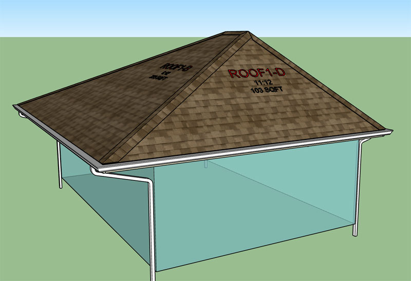
Even with the different overhangs and top plate heights the gutter height (fascia) is the same height all the way around. However the downspouts on opposite sides of the roof are customized per the overhang on each respective side.
Tomorrow I will jump back into the hip and jack rafters and see if we can wrap this one up.
The good news is that the required code for the asymmetric hip and jacks already exists. I will be borrowing from the roof return module where I handled dissimilar pitches. The bad news is that after a cursory review of this block of code I have absolutely no idea how it actually works anymore (I haven't looked at it in about 2 years). It's just a matter of reverse engineering my own code for about an hour and it will all come back to me.
-
I'm actually still working on the hip rafters. The complexity of a multi-pitch roof took another unexpected turn with the realization that when roof planes A and B are different pitches it causes an offset in the rafters at the peak which requires some additional logic to account for this fact with the placement of the hip rafters and their geometry.
I'm also still a bit conflicted on how to best handle the birdsmouth cut of the hip rafters when they walls have different top plate heights. In some cases the hip rafter misses the corner entirely and is askew on one of the walls, this is the simple case. In other cases the hip rafter technically rests at the "corner" but since there are two different wall heights possible it is not clear how the birdsmouth cut should be constructed exactly. I'm assuming that the higher plate height will govern.
Does anyone have any photos or details of actual construction where a hip rafter bisects a corner where the top plate heights vary?
-
Got me looking for examples. I've created (or passed on) far more problems like this for others, than I ever had to deal with in the field. You might look at this guys webpage. https://deskgram.net/explore/tags/bastardhip
-
Note how this hip rafter sits askew, only on one wall:
-
Yes. I once did a little roof framing, using old school framing square methods from a book. Sometimes I just had to work it out in the field.
-
When the hip roof is asymmetric across the ridge you end up with a situation like what is shown below:
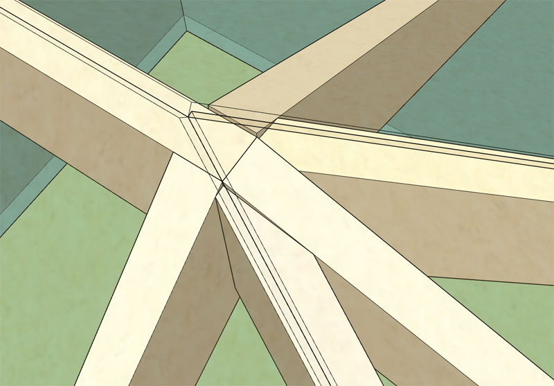
The common rafter in the upper right is a 7:12 pitch and the common rafter in the lower left is a 10:12 pitch. Normally with a symmetric hip or gable roof the common rafters would be flush with the top of the ridge board.
However in the asymmetric case the steeper pitched side is flush and the lesser pitched side overshoots the ridge board just slightly as shown. This additional asymmetry causes further complications in the calculations of the hip rafter that is adjacent to the overshooting common.
Also note that the seams in the sheathing (edges of the roof planes) do not center up on the ridge board or hip rafters. This is not a flaw or an error it is just the way the asymmetric roof goes together.
It appears that I have the hips correctly calculating now (after nearly two days of intense debugging and about 10 sheets of engineering pad) however tomorrow I will continue with further testing, to see if I can break anything, and then begin attacking the jack rafters.
A further look at the bird mouth cut question in shown in the example below:
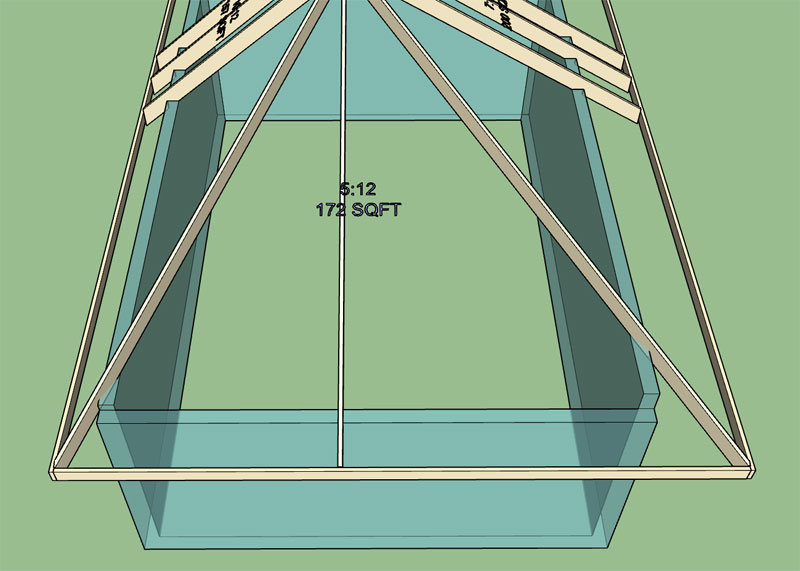
So in reality I am still missing the birds mouth cut for the hip rafters and the implementation of the soffit cut for trimming the tails of the hip rafters. Always too much to do and never enough time to get it all done.
I'm really hoping that the jack rafter piece is a lot less trouble than the hip rafters, I would really like to get this roof type wrapped up by the end of the weekend.
-
Since each hip rafter is potentially unique each one requires the following calculations (for those that are interested):
@Returnext = @HipendX + @Overhang3_num
@Returnext2 = (@Pitch3/@Pitch) * @Returnext
@Returnexthip = sqrt(@Returnext * @Returnext + @Returnext2 * @Returnext2)

@Zeta = acos(@Returnext/@Returnexthip)

@Tcy4mod = 0 - @Fascia_width * (tan(@Phi) - tan(@Phi3))
@Returnext2mod = @Tcy4mod/(tan(@Phi))

@Zeta_a = atan((tan(@Zeta))/(cos(@Phihip13)))
@Zeta_b = atan(tan(@Zeta)*cos(@Phihip13))
@Iota = atan(sin(@Zeta)*tan(@Phihip13))
@Kappa = atan(cos(@Zeta)*tan(@Phihip13))

@Term1 = (cos(@Zeta_a))/(cos(@Iota)) + ((sin(@Zeta_b))/(cos(@Kappa))) * ((tan(@Phi) - tan(@Iota))/(tan(@Phi3) - tan(@Kappa)))
@Abar = @Ply/@Term1
@Hipoffsetx = (@Returnexthip - @Ply) * sin(@Zeta)
@Bbar = @Abar * ((tan(@Phi) - tan(@Iota))/(tan(@Phi3) - tan(@Kappa)))
@Ebar = @Returnext - ((@Returnext2 + @Returnext2mod - @Abar)/(tan(@Zeta)))
@Fbar = @Returnext2 + @Returnext2mod - (tan(@Zeta))*(@Returnext - @Bbar)

if @Phi2 > @Phi
	@Zbar = @Ry4 - @Ry4r
	@Xbar = @Zbar/(tan(@Phi))
	@Bbarmod = ((@Abar+@Xbar) * (tan(@Phi) - tan(@Iota)) - @Zbar) / (tan(@Phi3) - tan(@Kappa))
else
	@Zbar = 0
	@Xbar = 0
	@Bbarmod = @Bbar

end

@Exthip13 = ((@Xbar+@Abar)*cos(@Phihip13)/tan(@Zeta))/(cos(@Phialpha1_3)) - @Zbar/(tan(@Phihip13))
Term1 of the Abar equation is really interesting. If I took the time I could probably condense down some of the variables and reduce the amount of algebra but then in the future it would be harder for me to follow, so it is best left as verbose as possible for myself and future generations.
The terms Abar, Bbar, EBar and Fbar specify the compound bevel cuts at the peak and eave of the hip rafter.
-
Actually I stand corrected. The sheathing does center up on the ridge board provided that you do vertically offset the opposing common rafters as shown in the previous images. A top down view shows the result:
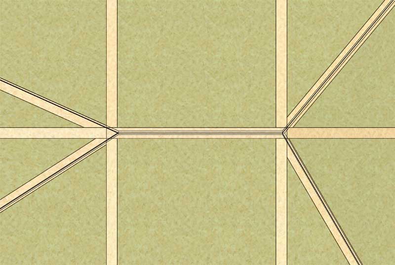
If you don't vertically offset the commons and the pitch on plane A and B differ then the ridge board will not center up on the sheathing. For now I have it centering and a vertical offset, for future work I may provide an option to toggle between these two possible configurations.
Here is a view of the other side of the roof, note the different top plate heights and where the hip rafters land on them and the corners:
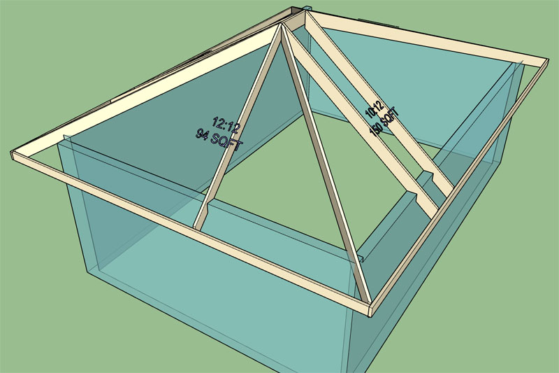
Better yet, go ahead and download my test model that was most recently generated by the new asymmetric module:
3D Warehouse
3D Warehouse is a website of searchable, pre-made 3D models that works seamlessly with SketchUp.
(3dwarehouse.sketchup.com)
-
First look at the jack rafters:
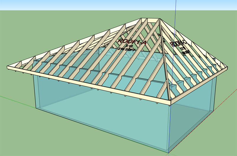
Next I will look at the birds mouth cut of the hip rafters and the soffit cut for both hip and jack rafters, then a bit more testing to see if anything can be broken when the degenerate case (symmetric roof) is calculated.
These is also the case where you might end up with a negative overhang (which doesn't make sense). I should probably include some logic to try and detect this condition and alert the user that the roof configuration is not physically possible.
-
The birds mouth cut algorithm (and code) is now functional however I can't say I'm completely satisfied with it yet.
For example take a look at this scenario:
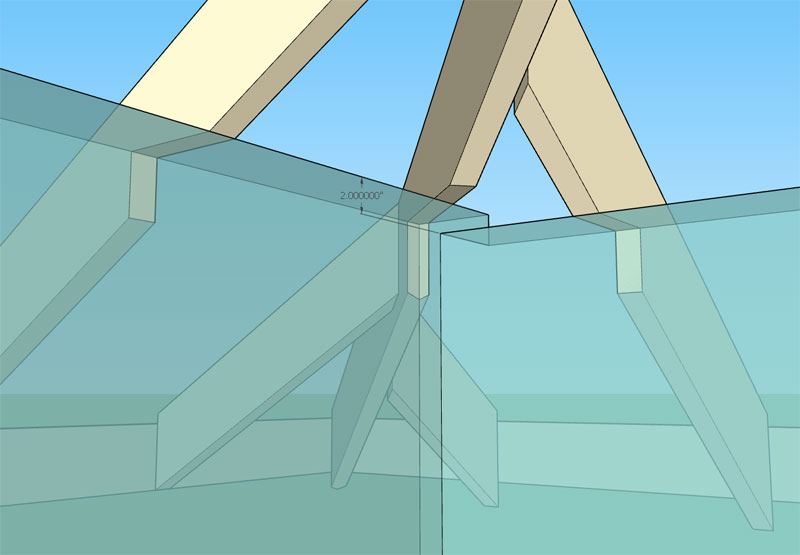
You have a 8:12 and 7:12 meeting almost at the corner of the building (skew is minimal) however the plate height is 2" higher on the 7:12 side and my algorithm cuts the birds mouth per the highest plate height at the corner.
In this particular case it would seem to make more sense to cut the birds mouth at the lower plate height otherwise not enough meat is left in the hip rafter. This algorithm may need further refinement to really make it meaningful and useful to the designer.
The other option of course is to simply not cut the birds mouth in the hips rafters and leave it to the user to determine what or how they want to handle the intersection at this critical junction.
The soffit cut in the case of a hip roof is actually quite simple (surprisingly). Since the fascia lines up all the way around the roof the soffit cut will also be the same height for all jacks, commons and hip rafters.
-
The soffit cut function is now active for hips, jacks and commons:
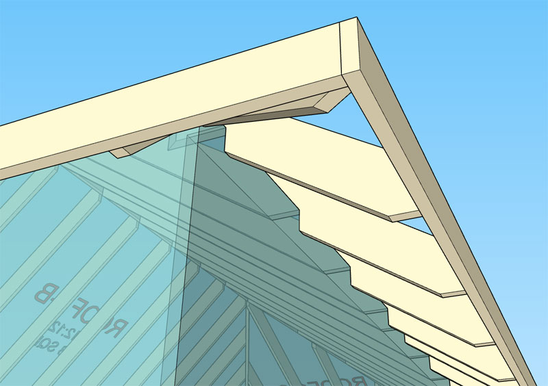
Now I will see if I can break the module, I'm sure there is some state or configuration that I haven't considered that may throw some errors.
-
Version 2.3.7 - 05.13.2019
- Enabled asymmetric hip rafter roofs (imperial and metric units).
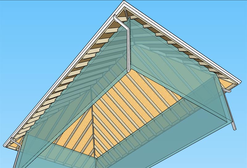
The most degenerate version of the asymmetric hip roof would be a pyramid roof. The roof shown below is a pyramid roof that is actually an asymmetric roof, as you can see the algorithms degenerate gracefully as they should:
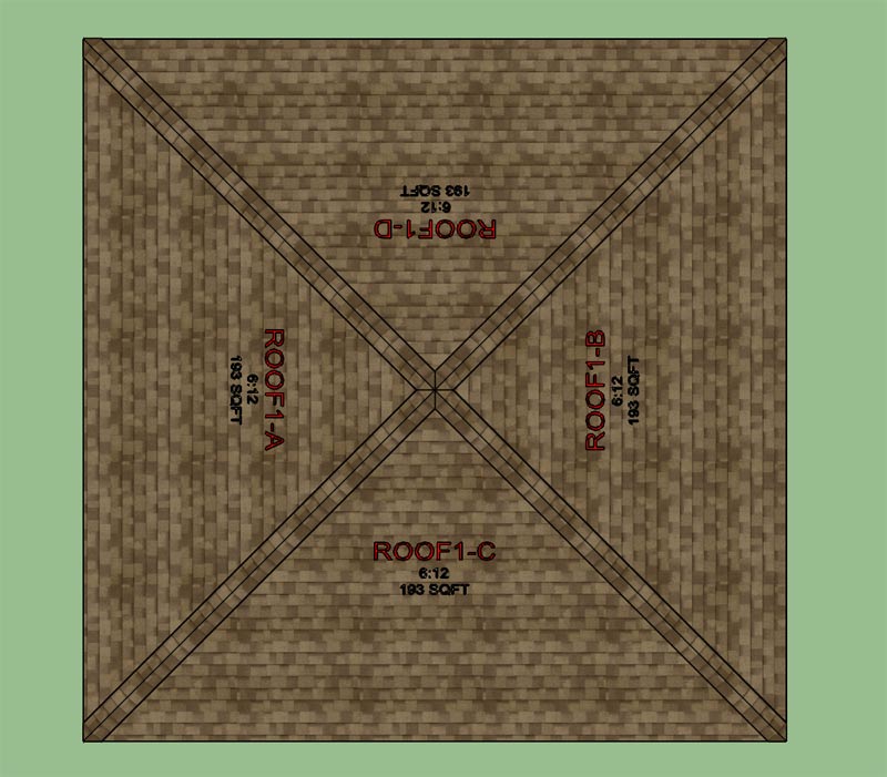
Items for future work include the ability to toggle the configuration where the sheathing centers up on the ridge board or not.
Another outstanding item is ceiling joists. I'm not even sure what do with ceiling joists yet for an asymmetric hip as there could possibly be four different ceiling joist heights.
I would also like to switch everything to HTML menus. The initial draw menu is still using the default SU GUI. Due to its limitations you can only initially create symmetric hip roofs but then you can edit them to switch them to an asymmetric configuration. I will explain this further in an upcoming tutorial video. Once I switch to an HTML draw menu this limitation will be resolved.
-
Download or view a sample of an asymmetric hip roof here:
3D Warehouse
3D Warehouse is a website of searchable, pre-made 3D models that works seamlessly with SketchUp.
(3dwarehouse.sketchup.com)
-
I've fixed a few small bugs with the jack rafters near the corners and re-released the plugin.
When the jack rafters approaches a corner and then the overhang portion of the roof the various permutations in the way the jack rafter is beveled or cut becomes quite interesting. With a regular symmetric hip roof the possible configurations is more limited and predictable however the asymmetry lends itself to additional cases, so more conditionals are required in the code to account for them.
I've ran some additional checks to try and ferret out these additional configurations and then provide the appropriate logic to handle them, however there may still be a few that may have eluded my best efforts. This module is new so there may still be a few fires yet.
-
Tutorial 15 - Asymmetric Hip Roofs:
In this video I try to explain how each roof plane can be adjusted and the details of toggling between auto calculating the overhang or the top plate height.
View model here:
3D Warehouse
3D Warehouse is a website of searchable, pre-made 3D models that works seamlessly with SketchUp.
(3dwarehouse.sketchup.com)
Looking at hip roof again this afternoon it occurred to me that it probably would be useful to have the ability to specify the depth of each hip rafter individually and for a symmetric roof the ability to specify the hip rafter depth independent of the common rafter depth. Yet another item to add to this modules todo list.
I also need to update the estimating module for this roof type (symmetric and asymmetric), the quantity and length of each jack rafter would be useful information.
-
Giving some thought to the secondary roof tool:
-
Trying to come up with an intuitive method for specifying a secondary roof. My idea is for the user to select the wall corners (1) and (2) that the projecting (secondary) roof will be bearing on and then to select the roof plane of the primary roof that the secondary roof should intersect. Essentially three points/picks will specify the secondary roof.
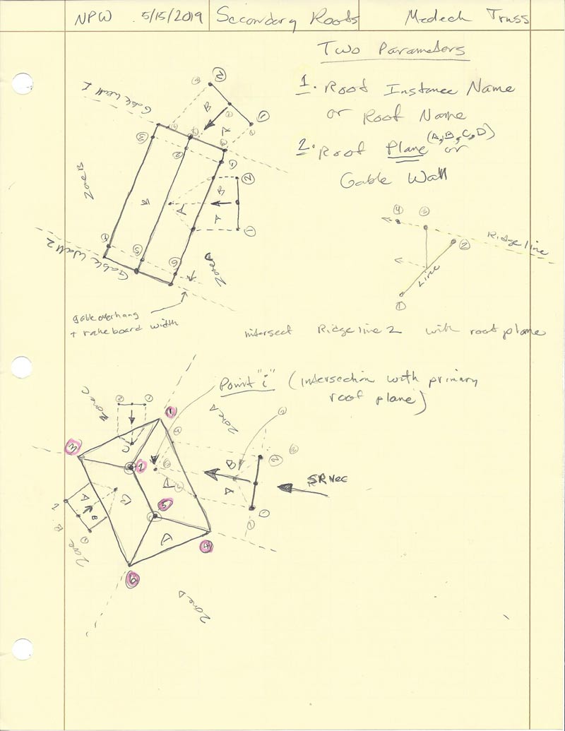
When a secondary is created it will store the primary roof name it is intersecting with as well as the roof plane. Either of these can then be modified in the secondary roof menu in the case that the user wants to switch to a different primary roof or a different roof plane of a given primary roof.
When a secondary roof is edited or regenerated it will then re-analyze the entire geometry with the specified primary roof and roof plane in order to generate the secondary roof geometry. This will allow the user maximum flexibility (ie. moving primary and secondary relative to each other {x, y, or in z} as well as changing the primary).
Orthogonal intersections are nice but we can't count on them so from the get go the secondary tool will be designed with any arbitrary intersection angle in mind as well as intersections with a roof planes or gable ends of a gable roof (wall).
Additionally, the secondary roof may be symmetric or asymmetric so it makes sense to also allow for this possibility as well.
One could even go so far as to allow for intersection with more exotic primary roofs (eg. gambrel, arched, polynesian etc...) however at this point I think I will limit myself to just a single pitched roof plane or wall plane.
There will be a separate tool for secondary hips and one for secondary gables, the reason being the vast number of different parameters required for each type of roof and the different algorithms required as far as calculating the actual roof rafter geometry.
At this point I am mostly conceptualizing and trying to see if there are any major holes or flaws in this system or method of secondary roofs. I would be interested to hear your feedback on the matter and especially if you can see any major problems with my methodology, or have suggestions for something that may work even better.
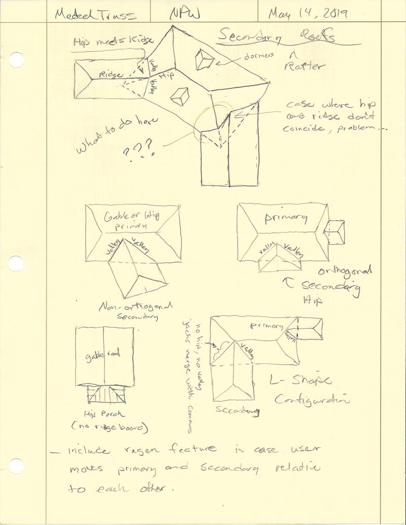
As can be seen on my previous notes page (May 14), there are a few special cases that will also need to be dealt with:
1.) Secondary roof is non-orthogonal to the primary roof and its ridge coincides or meets a primary hip. In this case the secondary really should intersect the two planes on each side of the primary's hip.
2.) A hip roof secondary meets a gable wall such that the aspect ratio of the secondary precludes it from having a ridge board perpendicular to the gable wall. There is also potentially the non-orthogonal possibility but this would not be very common.
3.) Typical L-shaped hip roof where the valley and hip theoretically merge into a common roof.
If I can somehow pull this one off, it will be a bit of a game changer for the Truss plugin since it will then allow for much more complicated rafter roofs.
Advertisement


