Alpha transparency in back face
-
I am unable to figure out how SU decides the transparency of a face.
It seems that "if" there is transparency in the back face SU chooses to use it.
It 's true?
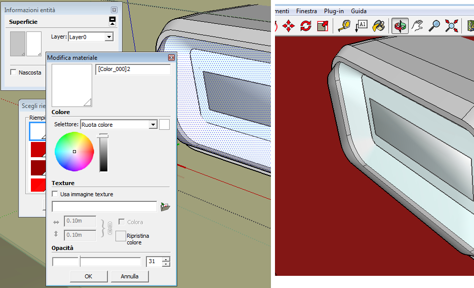
This is a model in which the transparency is declared only on the back of the glass, but it is applied to the right view.
https://3dwarehouse.sketchup.com/model.html?id=607f2b88312dd468bb5c0bf5eec83fc
thanks in advance!
-
@soldatino said:
I am unable to figure out how SU decides the transparency of a face.
It seems that "if" there is transparency in the back face SU chooses to use it.
It 's true?
This is a model in which the transparency is declared only on the back of the glass, but it is applied to the right view.
https://3dwarehouse.sketchup.com/model.html?id=607f2b88312dd468bb5c0bf5eec83fc
thanks in advance!I believe that SketchUp handles transparency independently on the "front" and "back" surfaces of a Face. For example, you can paint the inside of the walls of a room with an opaque material and the outside with a transparent or translucent material and then "look through" the walls from the outside but see them on the inside.
-
ok, thanks I think you're right, I try to run tests based on OR between external and internal, to understand if different values between outside and inside which is adopted. I thought at first that this was such a strange coincidence, and the possibility of difference in value as a general principle was implemented to allow view points from inside the objects. Thanks!
sorry my English is poor and wrong reasoning a bit complex.... -
If you paint the front of a face with a transparent material, and the face's back material is 'default', then both faces will appear transparent.
If you paint the back of a face with a transparent material, and the face's front material is 'default', then both faces will appear transparent.This simplifies making 'glass'...
If you paint the front of a face with a transparent material, and the face's back material is either already, OR is subsequently, painted with some other material, then only the front face appears transparent.
If you paint the back of a face with a transparent material, and the face's front material is either already, OR is subsequently, painted with some other material, then only the back face appears transparent.This also applies to any 'default' front/back faces within a group or component-instance, which itself is painted, so that the container's material permeates down onto the 'default' parts of any faces...
-
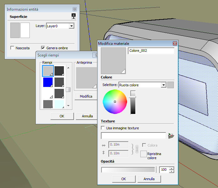
Now I am confused again. In my example above the front is grey... coloured, and 100% opaque, but the glass get the transparency from the back.
The grey is "default"? It is painted.
What is the concept of default in SU?
-
but perhaps it is possible that the opacity of the gray does not matter because the grey is inherited from the block...
-
The 'default' material colors for front and back sides of faces are set in the Style.
Just because you make another material that is the same color 'grey' it means nothing.
A 'default' material face will display using any transparent material applied to its 'other side'.
But if that face's side has a material applied, then it is used in preference to the transparent material on the 'other side'.
I think you are over thinking this... -
thank you but I still absolutely do not understand.
Who made this object used a grey color with 100% opacity on the front face, and a white color with a transparency value on the back. Following this the face has become transparent.
Maybe I never understood the difference between material and color .... I'll have to start studying that ... thanks -
There is only 'Material'.
Every material has a 'Color'.
Additionally material can also be given a 'Texture' - an image-file that adds things like a tile-pattern etc.
That can then be adjusted in its XY size...
Any 'Material' can also be given reduced 'opacity', so it is then 'transparent'...
You can edit/make Materials in the Materials Browser...
You paint things with Materials.
Painting something with the 'default-material' effectively makes that object have NO material...The one unusual 'material' is this 'default-material' - this is setup in the Style.
This sets the color for things that otherwise does not have a material painted onto them.
Faces are different from edges, they have a front-side and a back-side - you normally model so that the back-side is not seen...
The front-side color is normally an off-white and the back-side color is normally blue-gray - you can edit these in the Style's settings.
You can view the model in various 'modes' - from 'textured' down through 'colored' to 'Monochrome' where the default faces show [useful when trying to fix faces that are incorrectly oriented, and which would likely cause issues with Renders]
The default material cannot be transparent or textured.Faces painted with a Material will then have that material displayed on that side of the face.
You normally paint the front-side !
Exceptionally, if the face's material has any transparency then and if the other side of the face does not have a material assigned to it, then that side of the face is also displayed using the painted transparent material.Textured-materials applied directly onto a selected-face can be adjusted using Texture in the context-menu - positioned, rotated, scaled etc... e.g. getting wood-grain textures to run in the desired direction... This is often called UV-mapping.
'Containers' like Groups and Component-Instances can also be painted with a Material.
Faces within the painted container which do not have a material assigned to them will still have no material, BUT they will display the container's material.
You cannot 'map' a container's textured material.
Faces with a material assigned to then are unaffected by their container's material.
An example of this would be a Car component, made with the default-material on its body parts, but colored materials on other parts like tires, hubs, bumpers, lights, glass, seats etc.
You can now place several instances and they all look the same, with off-white body-work, but you can paint individual instances any desired color; so you can then have red, blue, gray cars using the same component-definition, and they all still show the same materials on the other parts...Nested containers also take the material of their own container - if any.
-
Ok, thank you for patience and useful general explanation.
Now even though I understood the mystery of the face "internal".
Who had designed the glass had done it in reverse ....
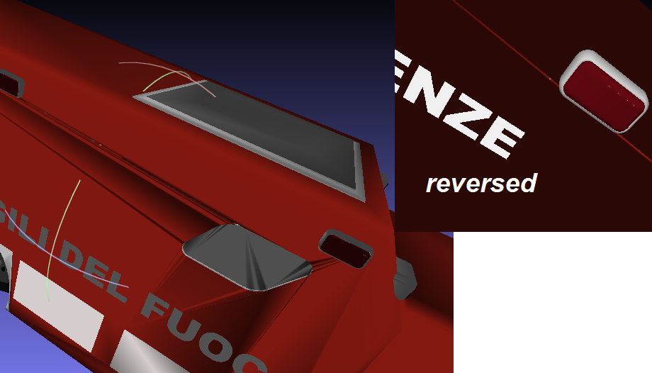
I turned the object into STL format and I checked the normal in MeshLab.
On MeshLab the glass appears "broken", as all faces reversed, MeshLab does not reflect light for it. For this reason, the transparency on SU is active, in fact transparency appears on the right, but the faces are reversed.
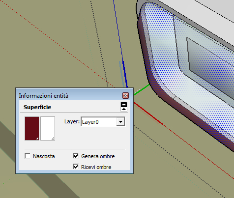
(in the small image, I reversed the normals)In SU (second upload) this concept is obvious if I try to change color, the color in the palette is at left side (first), I thought was the main (front face) but the face that paints is the (false back) inside.
-
The piece of the puzzle that you may still be missing is that Faces in SketchUp also have an associated normal Vector3d that defines "front" or "outside". On the entity info window, the material painted on the "front" shows in the left panel, and the material painted on the "back" shows on the right panel. From your SketchUp picture it is evident that what one would logically call the "inside" of the window is actually the "outside" in terms of SketchUp Faces. That is, the brown-red color shows where the inner surface is visible and the transparent color where it is not. Your Face normals are pointed inward. You need to reverse all of the Faces of your window by means of the right-click context menu in SketchUp.
-
thanks, this is not a model of mine, who did it drew partly in one way and partly in another. I was looking for a test of my format converters, but I think that if I wont to do a perfect job I also need to search the SU API that gives me information about the "normals" of the faces drawn that I must translate...
The confusion starts from the fact that I see contradictions, it is not easy to explain.
I isolated the glass and I'm sure.- face.back_material.alpha - declare a value of low opacity for the "back" of the face, and it is exact because the face is designed relatively to this side, and has vertices in reverse order if we look at the truck from the outside.
But the same face on the window of colors of SU is shown with the back color on the left, as if it were the primary side of the face, that instead is completely opaque.
I conclude that to test the proper operation of my parser does not have to look at the order used by the window that I showed above.
http://sketchucation.com/forums/download/file.php?id=125617 -
@soldatino said:
thanks, this is not a model of mine, who did it drew partly in one way and partly in another. I was looking for a test of my format converters, but I think that if I wont to do a perfect job I also need to search the SU API that gives me information about the "normals" of the faces drawn that I must translate...
The confusion starts from the fact that I see contradictions, it is not easy to explain.
I isolated the glass and I'm sure.- face.back_material.alpha - declare a value of low opacity for the "back" of the face, and it is exact because the face is designed relatively to this side, but has vertices in reverse order if we look at the truck from the outside.
But the same face on the window of colors of SU is shown with the back color on the left, as if it were the primary side of the face, that instead is completely opaque.
As you draw a Face, the ordering of the vertices ordinarily determines the orientation of the normal vector, hence the directions of "front" and "back". However, SketchUp sometimes flips the normal during its cleanup operations. For example, it will determinedly force the normal to point downward if you draw something on the z=0 plane. It will also flip normals to match where two Faces intersect. It will usually cause the normals to all point outward when you create a "solid". So, it always pays to check what you got and fix up any reversals, especially before doing things like applying translucent materials that can confuse the issue!
In ruby code it is not uncommon to have to test whether a normal came out the way you assumed. For example, a positive push-pull value goes in the direction of the normal vector. If SU set it opposite to what you assumed, your operation will also go opposite.
In the case of your converter, it seems to me that you can't make assumptions about what the creator of the original model intended. If they modeled a particular way, maybe that is what they meant!

-
No, I do not assume anything, I follow what APIs tell me, but it is not ok, because a face drawn as transparent from the inside OF THE TRUCK, SU shows transparent from outside OF THE TRUCK.

This makes it a bit difficult to make the correct view on other platforms.
Don't care of the code in surplus, I just need to relate to integer (part of 100) for my needs ....
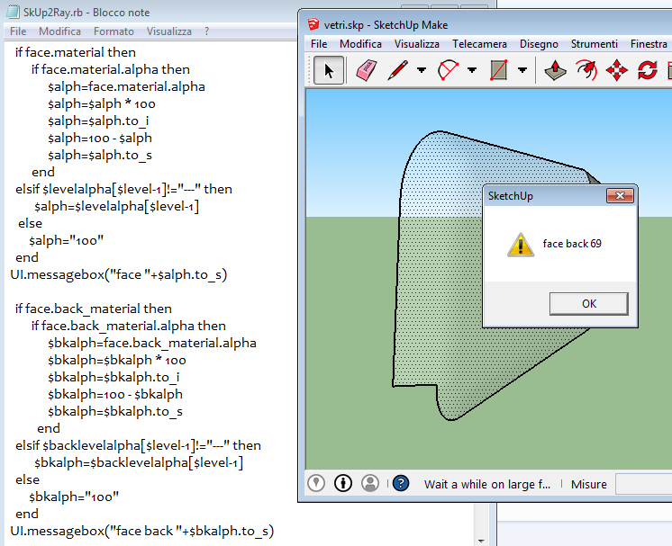
-
Now you are feeding us more information in tiny morsels.

In most renderers you only get the front face rendered in its color/texture, any back face is usually shown in white/black/default/transparent material depending on the rendering-application used.
It is therefore important that 'visible' faces are front faces.
If you are making glass that will be view from both sides it should have a real thickness, like in the real world, with both of its faces looking outwards.
If you have any single face then its back view in a render may well look different from how it renders in SketchUp.
If you view the model in Monochrome mode using a Style with a distinctively colored default back-face material, you can more readily see what faces are incorrectly oriented.
There are several tools to reverse such poorly modeled faces.In code you can ensure a face's normal is towards the camera [get angles between the view direction and the face.normal], if >180 you are looking at the front !
In code you can also paint the same material on every face's back as it is front.
So for example iterating all faces to make sure any ones using a transparent material, then have the same material on both sides...
faces.each{|face| face.back_material=face.material if face.material && face.material.alpha < 1.0 **&& !face.back_material** }
The part at the end -&& !face.back_material- only paints the back of a face if it is in already in the default material, BUT omitting it forces every face which has a transparent material to have that material on its front AND its back sides.You can of course do much more, but that's just one idea......
-
@tig said:
In code you can ensure a face's normal is towards the camera [get angles between the view direction and the face.normal], if >180 you are looking at the front !
yes, I think that this is really a good idea.
I thought for a control vector from the center of the object, but it is not a general rule, if the object has undercuts ...
instead your idea can not fail
-
@tig said:
In code you can ensure a face's normal is towards the camera [get angles between the view direction and the face.normal], if >180 you are looking at the front !
TIG, strictly this is only true for a parallel projection. Its broadly correct for perspective projection, but not for all cases.
-
@tig said:
In code you can also paint the same material on every face's back as it is front.
So for example iterating all faces to make sure any ones using a transparent material, then have the same material on both sides...
faces.each{|face| face.back_material=face.material if face.material && face.material.alpha < 1.0 **&& !face.back_material** }
The part at the end -&& !face.back_material- only paints the back of a face if it is in already in the default material, BUT omitting it forces every face which has a transparent material to have that material on its front AND its back sides.And of course this ignores Group materials that override any face with the Default material. So you can't just check when face#[back_]material is nil

-
You are right about the angle check.
I threw it out as a way of approaching something - NOT a fully fledged working tool/method...However, this could be further improved by not using the camera direction vector, but getting the vector between the eye and parts of the face [like bounds.center or vertices] AND the angle_between each of those and the face.normal ?***
Didier Bur's 'Automatic Face Reverser' in the PluginStore works by using a pickray within a Tool t and inspects the visibility of every vertex in a face, casting the ray from the eye, until one is visible AND the normal is looking away from the camera [>=180.degrees], then you are looking at a visible bare back...
Didier's file's code is 'packed' as a low level encryption, but by making a copy and changing the file suffix to .txt so it doesn't load, and editing the initial 'eval' to a 'puts', will then 'unpack' its contents and print it out in the Ruby Console when you use 'load' on it later...
Note his tool only works on the active_entities or selected faces, and also has an option for multiple eye-point checking etc... -
@adamb said:
@tig said:
In code you can ensure a face's normal is towards the camera [get angles between the view direction and the face.normal], if >180 you are looking at the front !
TIG, strictly this is only true for a parallel projection. Its broadly correct for perspective projection, but not for all cases.
Yes, but the summ of the perspective projections draw step by step the outer visible skin of each object, only if you are "into" the object the entire skin is reversed.
I think that it is the right method to identify if the face is drawn properly...
Thus, in case of doubt with transparency valued only on the back of the face, checking if the face was drawn wrong then I can understand why transparency is over just that way.
And this is precisely the case of the glass of the truck that was giving me uncertainties.PS. inherited attributes are one other thing to consider, but if you take a look at my code you see that I have a map levels that store the parent attribute, and only if the face need it, I load that value
Advertisement


