Making Spaced Bar Footrail Brackets.
-
Hi everyone,
I am new to this forum and to Sketchup and I am finding it a wonderful resource. I am a web developer who has been given a project involving the creation of a mall kiosk sandwich/coffee shop. It is round and I am struggling badly.
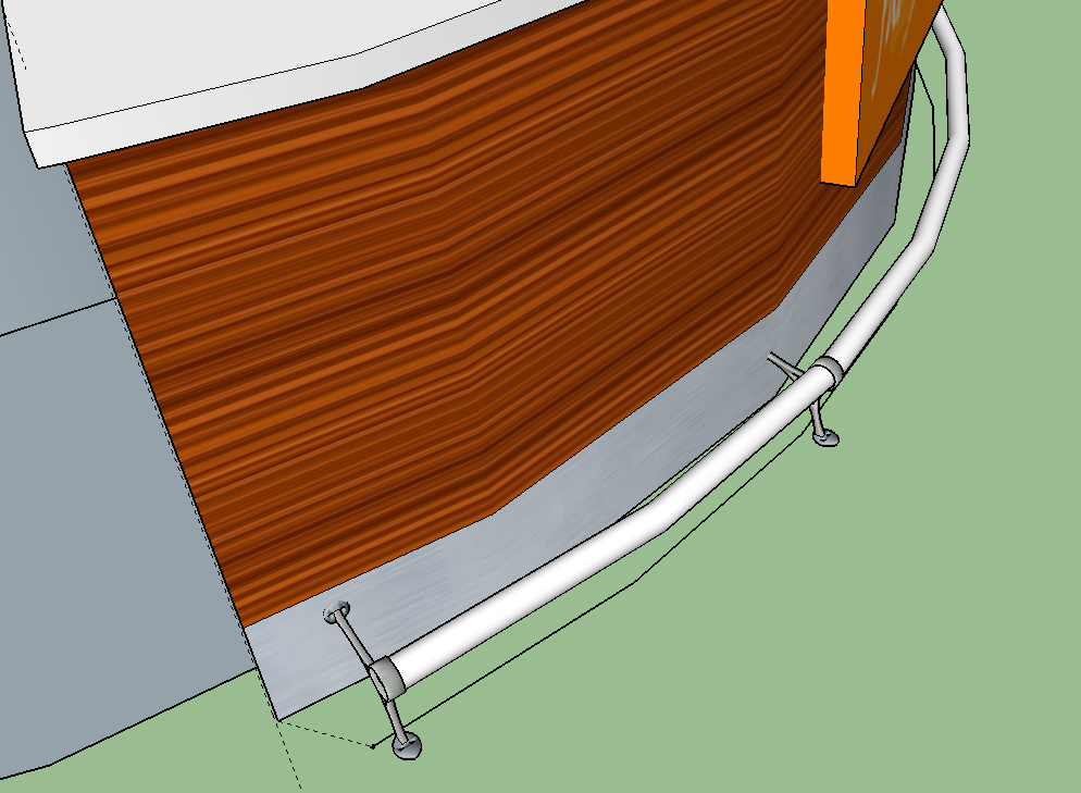
I have been using Sketchup only a few days but I am struggling to add a bar footrest for the back seating area. I created a curve, away from the main bar and then used follow me to create the tubular shape for the bar. I then imported a footrest bracket but the problem is that only the ends of the footrest fit the bracket, with everything in between being too small and merging into the main bar. I hope I explained this right but I have been googling tutorials to learn this and I couldn't find anything on this.
I attached an image for help, any info would be greatly appreciated as I am time sensitive on this and had it all dumped on my when I am not properly trained!

-
One option would be to redraw the rail using more segments in the path so it is smoother. Make the diameter of the foot rail the same as hole in the bracket. Then don't place the brackets on the vertices along the path.
Also, there's an important little detail about using Follow Me. The profile needs to be place perpendicular to the first segment in the path and the end of the extrusion will be perpendicular to the end segment in the path. If you don't place the profile perpendicularly to that first segment in the path, SketchUp will project (not rotate) the profile to perpendicular. This will change the shape of the profile and also the size.
-
Thanks for the reply, How do I add more segments using follow me? I have not seen a feature like that. Also what do you mean by " then don't place the brackets along the vertices of the path". I am actually trying to manually add each bracket first, spaced 3' apart and then build the bar through the holes via curve. Not working out too great though. I am finding making things accurate for building to be very difficult.
-
You'll have to redraw the path and add more segments. If the path is being drawn with the Arc tool, you can change the number of segments before you start drawing it. If you are drawing that path some other way, you'll have to use a different method to set the number of segments.
As for the vertices, you can that your curved path is made up of a series of line segments. Where they meet there's a vertex. This is a place where you extrusion changes direction so the profile won't be exactly the same size as the rest of the rail. Think about in reality, take a rod and cut an angled end for a miter. The face will be larger than if you cut square across. If you've drawn the rail so it is the same diameter as the hole in the bracket, the rail will be slightly wider at the vertices.
It is entirely possible to make your model with high precision but you might want to consider the application for the model. If the audience for whom you are making this drawing is only going to look at the overall bar, these little details you're working on won't show. Maybe there's not much point in spending a lot of time on this foot rail. Will what you've drawn convey the needed information? Ifso, move on to some other part of the drawing. The bracket is probably going to be an off-the-shelf thing and the rail will be stock to fit. Unless you need a manufacturing drawing for the bracket and the rail, you might want to say it's close enough.
Advertisement


