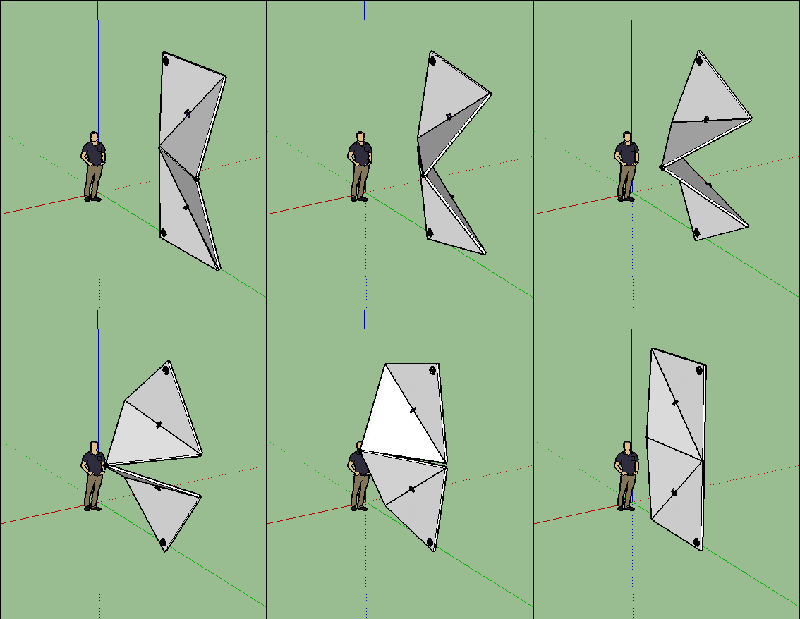
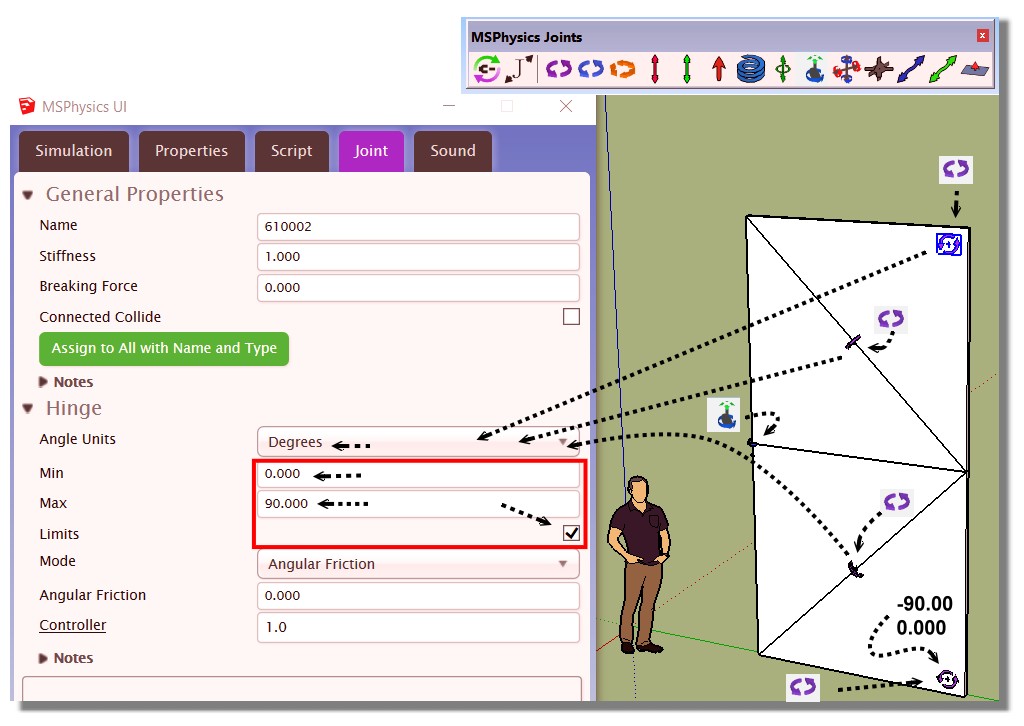
MSPhysics 1.0.3 (16 October 2017)
-
@ropefelt said:
Can I use this plugin to simulate nails in wood? I can't figure out which joint to use.
Yes you can, but the nails will not leave a hole in the wood. Just connect the nails to a piston joint and control them with a slider controller. Also, make sure the board or the nails are set to non-collidable.
-
Hi Anton,
A question for functions of a next version of MSPhysics:
Could it be possible to store transformations (translation, rotation, scaling) and manipulations off visibility on nested groups in the replay record data?
At present, these changes can be retained during an MSP session, played back and exported as a movie (frames), but disappear after saving, closing and reloading the replay data.
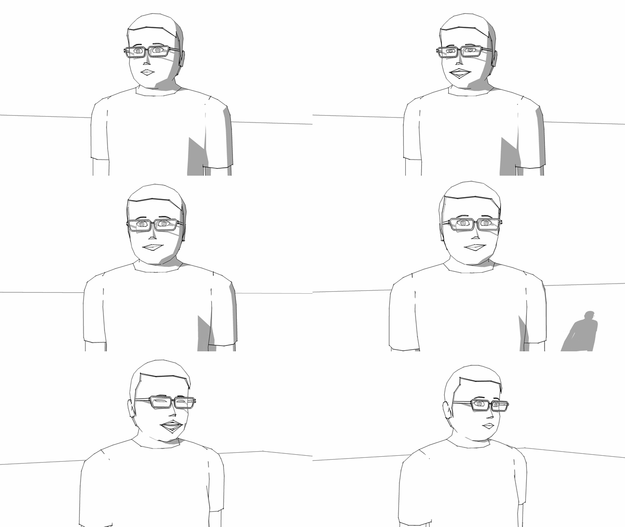
Here is an example of manipulating the visibility of embedded groups to achieve the effect of winking, if you want to test it.
Thanks!
-
@faust07 said:
Hi Anton,
A question for functions of a next version of MSPhysics:
Could it be possible to store transformations (translation, rotation, scaling) and manipulations off visibility on nested groups in the replay record data?
At present, these changes can be retained during an MSP session, played back and exported as a movie (frames), but disappear after saving, closing and reloading the replay data.
Here is an example of manipulating the visibility of embedded groups to achieve the effect of winking, if you want to test it.
Thanks!As far as I recall, you can already do that. In MSPhysics Replay Settings menu you can enable material record, style record, and other stuff. By default, only the camera and transformations are recorded.
Once you enable the recording, you will have to re-record, so that new data is recorded in your animation.
-
Oh, I don't think I've explained my problem clearly enough. I have to work on the translation. I meant the permanent storage of manipulations to subgroups in replay files. These are lost after closing the model file and later opening and loading the replay data.
-
Anton....firstly thanks for your AMAZING plugin. It is unbelievable how fast it is even on low powered hardware.
I have slider controls which I have added programmatically using ControlPanel.add_slider and ControlPanel.get_slider_value(name) and they work fine, but ControlPanel.set_slider_value(name, value) fails with an error in the html of the control panel which says something like error cannot find sliders.
Is there a fault in the html/javascript/missing file or am I doing something wrong?
AN EXAMPLE OF HOW TO SUCCESSFULLY SET A SLIDER VALUE WOULD HELP A LOTsincerely
Sujit Vasanth
PS. I can get round it by destroying all sliders and rebuilding them, but the redrawing slows my program down,
-
Hello,
I've used MSPhysics for a simulation on my project, and now, even after disabled the plugin, my model keeps with a "Created with MSPhysics 1.0.3" message on the upper left corner, and i can't manage to remove it.
Do you guys faced it?
Thanks in advance.
-
@lvskk said:
Hello,
I've used MSPhysics for a simulation on my project, and now, even after disabled the plugin, my model keeps with a "Created with MSPhysics 1.0.3" message on the upper left corner, and i can't manage to remove it.
There's a layer called MSPWatermarkText - just turn it off
-
Great extension. How to remove watermark with text: "Created with MSPhysics 1.0.3" If there is option to buy it where I can find it?
-
Hello,
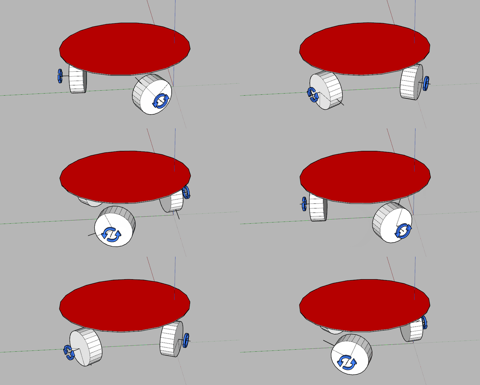
I am trying to simulate an omnidirectional 3WD robot in MSphysics using motors and cylinders to simulate the omnidirectional wheel as shown in the attached file. However, the robot does not move in a straight line when the front wheels rotate at the speed but in opposite directions despiste being symmetric. Does anyone have any suggestions of what I can do please ? Thank you in advance.
-
The model is designed to move in this way. Which wheels are the front wheels?
Click on the image to animate.
-
I am trying to model the robot shown in this video,(https://www.youtube.com/watch?v=l__IKY-Xrw4&t=5s)
i.e the robot should be a able to move in the x and y plane without rotating by varying the speeds of each wheel independently. I have updated the model by replacing the cylinder wheel with two spheres, one of the sphere is attached to a motor while the other motor is allowed to rotate freely. However, the model still does not move in a straight line?Do you have any suggestions of what could be the problem please? Or is there any other way of how I can move a circular disc representing the robot platform that is able to move in any direction and rotate on its own axis in order to be able to bypass the mechanism of the omniwheels while retaining the stability provided by the three wheels?
I appreciate your help and thank you in advance.
-
@anton_s said:
@oheimala said:
I have an issue with floathing items. I work as a professional with floating docks, and the MSP simulation in water is something I would really love to use; actually a perfect tool for me. But.. when making a pontoon with several materials, the simulation will give strange results. I believe there is a some kind of bug.
As attached is a simplified concrete pontoon of two parts: a shell of concrete and a float of styrofoam. When dropped to float, you see four different scenarios happen and none of them is accurate. From my point of view it would be easy if the simulation could work without calculation; just simply specifying the parts density, group them and let them float.
The shell must consist from five separate subgroups, that is from four wall groups and one base/ceiling group. The top level group should be assigned Compound shape. That way, the collision shape generated will reflect the actual one. If you enable collision wireframe in simulation, you will see what is going on. So if you convexify subgroups, your resulting simulation would be realistic and the density you assign will reflect the density of material properly.
Hi Anton, thanks for your kind reply. So; complex pontoon structures may be tiny nightmares for floating simulations if the structures must be made from small simplified convex parts... Okay - I will test when I have resources for it, and I'll report. Fredo Tools "Convexify" may be the key

-
@oheimala said:
@anton_s said:
@oheimala said:
I have an issue with floathing items. I work as a professional with floating docks, and the MSP simulation in water is something I would really love to use; actually a perfect tool for me. But.. when making a pontoon with several materials, the simulation will give strange results. I believe there is a some kind of bug.
As attached is a simplified concrete pontoon of two parts: a shell of concrete and a float of styrofoam. When dropped to float, you see four different scenarios happen and none of them is accurate. From my point of view it would be easy if the simulation could work without calculation; just simply specifying the parts density, group them and let them float.
The shell must consist from five separate subgroups, that is from four wall groups and one base/ceiling group. The top level group should be assigned Compound shape. That way, the collision shape generated will reflect the actual one. If you enable collision wireframe in simulation, you will see what is going on. So if you convexify subgroups, your resulting simulation would be realistic and the density you assign will reflect the density of material properly.
Hi Anton, thanks for your kind reply. So; complex pontoon structures may be tiny nightmares for floating simulations if the structures must be made from small simplified convex parts... Okay - I will test when I have resources for it, and I'll report. Fredo Tools "Convexify" may be the key

Hi again. Yes, convexifying the pontoon shell solved the issue - Thanks!! And a as a note to other users: the Convexify in the Fredo Tools plugin is a great help!
So; I keep testing floating simulations. The game will be harder when added more materials, complex shapes, anchor chains etc..
- Cheers! -
-
Hi
Now I have tested anchor chains for a while already. The chain links are convexified and their shape is simplified for better performance. The topmost shape of a link is compound. Links are built as components. Their mass control is by density (of "cast iron" due somehow "steel" has too high density in the preset values). The actual chain is accomplished with universal joints (based on the video tutorial https://youtu.be/TLB1LjFUjWM)).
As attached file is a setup of simplified "balance scale" with two, three and seven links chain. The balance weight is controlled by mass and set to same than links weight sum.
So: the balance remains well up to three links, but when added more of exactly the same links, the chain weight rises like rocket and the needed balance weight makes no sense

I am sure I am doing something wrong, but despite hours and hours of testing I have not found any solution.
Thanks again

-
Hi. I'm using MSphysics 1.0.3 with SU 2017 pro quite long time, but I still have a silly question:
When I'm starting again SU with my project, I would like to run replay of my last simulation recorded in the previous session (which recording was working perfectly then). I see [project_name].mspreplay file in the same directory as my project, but still when I'm restarting SU the replay arrow is grayed.
What to do to reopen saved animation in SU?
As for now to keep my animation in memory I run screen capture programs.
PS. I'm posting the first time question in this forum, so I need to add: thanks a lot for this awesome plugin Anton!
-
BruceRob40, thank you for the complement!
Every time you perform a simulation and record, acquired model data is saved to a separate file, [model name].mspreplay, at the same path as the model. Additional record information is saved in the model itself, to help associating file data with their entities. This means that, in order to preserve your animation, you must save your model after recording an animation. When you load your model again, the animation should load with it.
-
Hello everyone,
My problem is, i installed MSPhysics with no problem but it keeps deleted everytime i restart Sketchup. I am using 2017 Pro version. I can install it again from extension manager with no problems, i can use it with no problems, the things that i draw with MSphysics remains, but the extension get uninstalled after i restart Sketchup.
It is not a big problem since i can re-install it everytime in 30 secs but.. it is still annoying.
I would be grateful if someone can help me with fixing this problem, many thanks. -
-
Well done! Complex and simple at the same time. A good example of using MSPhysics.
-
@Anton
Not so bad!
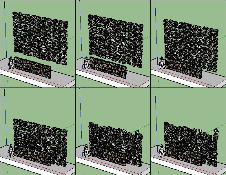
and after Eclate Deplace
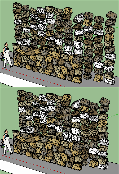
PS Have you something for "untouch" some objects with a measure given inside mS Physics?
Sure I have yet Eclate-deplace ...
Advertisement

