Linear dimensions that are on an angle
-
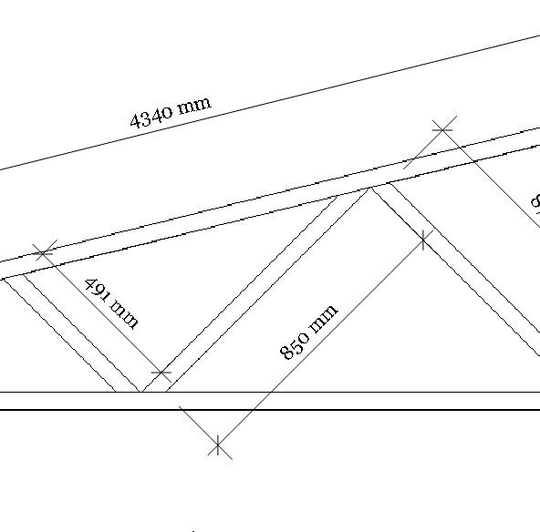
How can I accurately represent the length of a piece of steel in layout if both ends are cut as angles on opposite sides? See image:

I can get it to represent accurately if there is just one angle or if both angles are on the same side....but not two angles on opposite sides - a common requirement in a lot of joinery and steel framework -
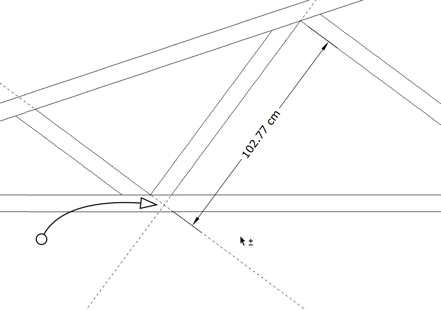
You're right. If you click on the desired end points, the dimension can't be made to align with the side of the part. I hope they'll fix it. In the meantime, here's a work around that shouldn't be too painful.
Place a couple of guidelines in the SKP model that intersect as shown. This will create a virtual corner to dimension to. After you've placed the dimensions, you can delete the guidelines and re-render or just render the viewport in Vector.

-
Glad that you've got a workaround but it is a bit clunky - especially when SU can do this dimension fine....
If I submit it as a bug fix for LO will people support it?
-
I expect it would get support but I wouldn't submit it as a bug. A feature request would be more appropriate.
I've found other cases where it is useful to create a virtual corner for placing a dimension and I'm thinking that at the very least, this method will always have some application.
-
I think this problem is common in CAD and different apps probably have different solutions. You are calling out two points, then you want alignment with a line that is actually not parallel with the points. It's a special case that hasn't been addressed along with many other dimensioning functions. Not a bug.
-
Good point, I shouldn't have called it a bug but a feature request.
Would many people support such a feature request? I guess it requires LO understanding the component axes from SU as this appears to be how such dimensioning is able to be interpreted accurately by SU
-
I can't speak for everyone but I would second the feature request.
I'm not sure about the component thing but maybe there's something there. I didn't make any components in my illustration and my drawing was only some lines on the ground plane.
-
Your explanation was another clever way to do it using guides.
What I mean by components is this:
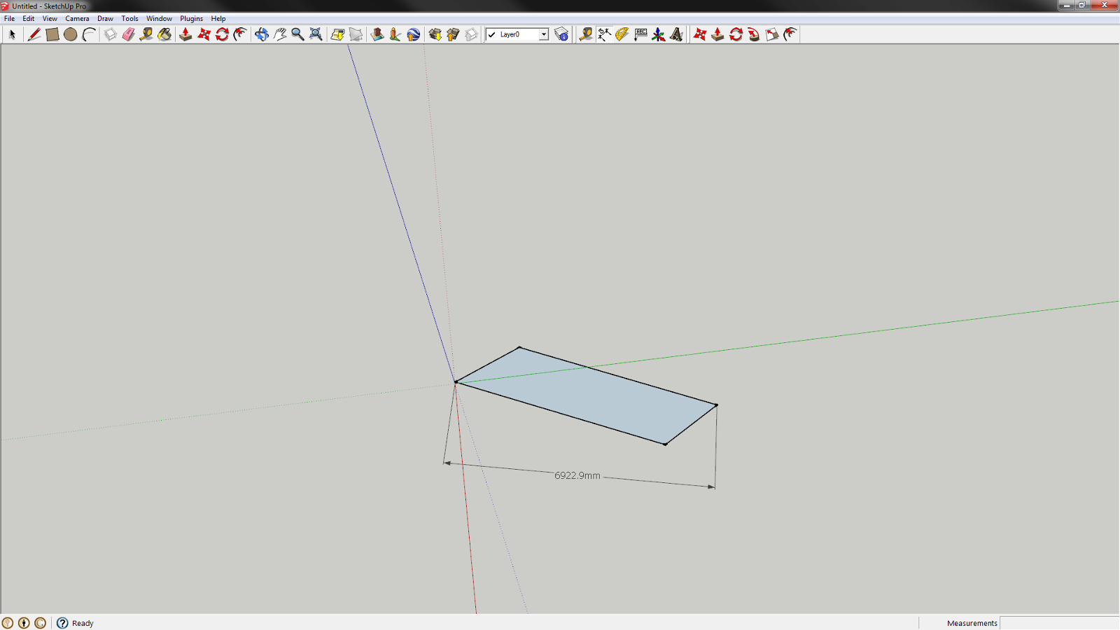
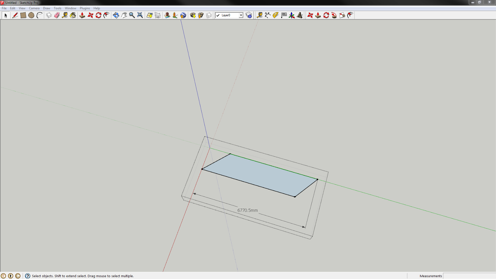
If you dimension a shape like we are describing in SU outside of the component it will give you a straight line dimension between the two points:

Basically in relation to the axes of the main model.But if you open the component and add the dimension within the component it references the component axes and you get an accurate dimension:

If you could somehow reference these component axes in LO perhaps LO could give accurate dimensions too....?
-
I see what you mean. Somehow it would be nice to have the ability to specify a line to which the dimension arrow would be parallel.
-
Yes! That is a great idea! Anyone here with the programming/scripting capacity to implement it?
-
Your example is great, and adding to my earlier point, the CAD I use has many angles that can be preset besides ortho. Dimensions can work to all preset angles besides directly between the pick points.
-
Here is the feature request - http://sketchucation.com/forums/viewtopic.php?f=13%26amp;t=56111
do I need to document it more fully within the request or can I simply reference this thread?
-
Good. I think the reference is probably fine but you might want to add your screen shot to that other post.
-
Well, it makes sense to me.

-
The other useful thing is in relation to angle cuts. If you cut a piece of steel or wood in a workshop cutting machine, a 90 degree cut straight across the material is considered 0 degrees so a slight angle might be 5 degrees. If you try to show this in layout you have to reference it from the edge of the material and so get 85 degrees or 95 degrees.
Some way of referencing a perpendicular cut as 0 would be very helpful when making cut diagrams for the workshop.
I have been working around this by using a modification of Dave R's methodology above in that I put in a perpendicular guide in SU, reference in layout, delete it in SU and "Update Reference" in layout but the ability to do this in some natural manner within Layout would be very powerful.
Am I making sense?
-
I updated the feature request - please support it!:
http://sketchucation.com/forums/viewtopic.php?f=13%26amp;t=56111%26amp;p=509418#p509418
Advertisement


