Lining things up
-
Sketchup probably just sees a collection of edges, not a circle. If you draw a circle, entity info will call it a circle, and you can use inferences on that. Imported circles are not necessarily SU circles ( IDK if they ever are). You might draw a matching circle over, but please note: intersecting HARD edges will break it up into arcs or edges. Not always helpful
 but that's how it is.
 -
Everyone- thank you for your help with this. I am having a much easier time lining things up using these tips and techniques. I think my major stumbling blocks were:
*the lack of a common center due to the imported Solidworks files
*the differences in the number of sides of the circles I was trying to align
*not knowing that SU would not recognize a Solidworks circle.I have also abandoned the size difference between the tube and the ring and am now keeping the OD of the tube and the ID of the ring equal to make things easier.
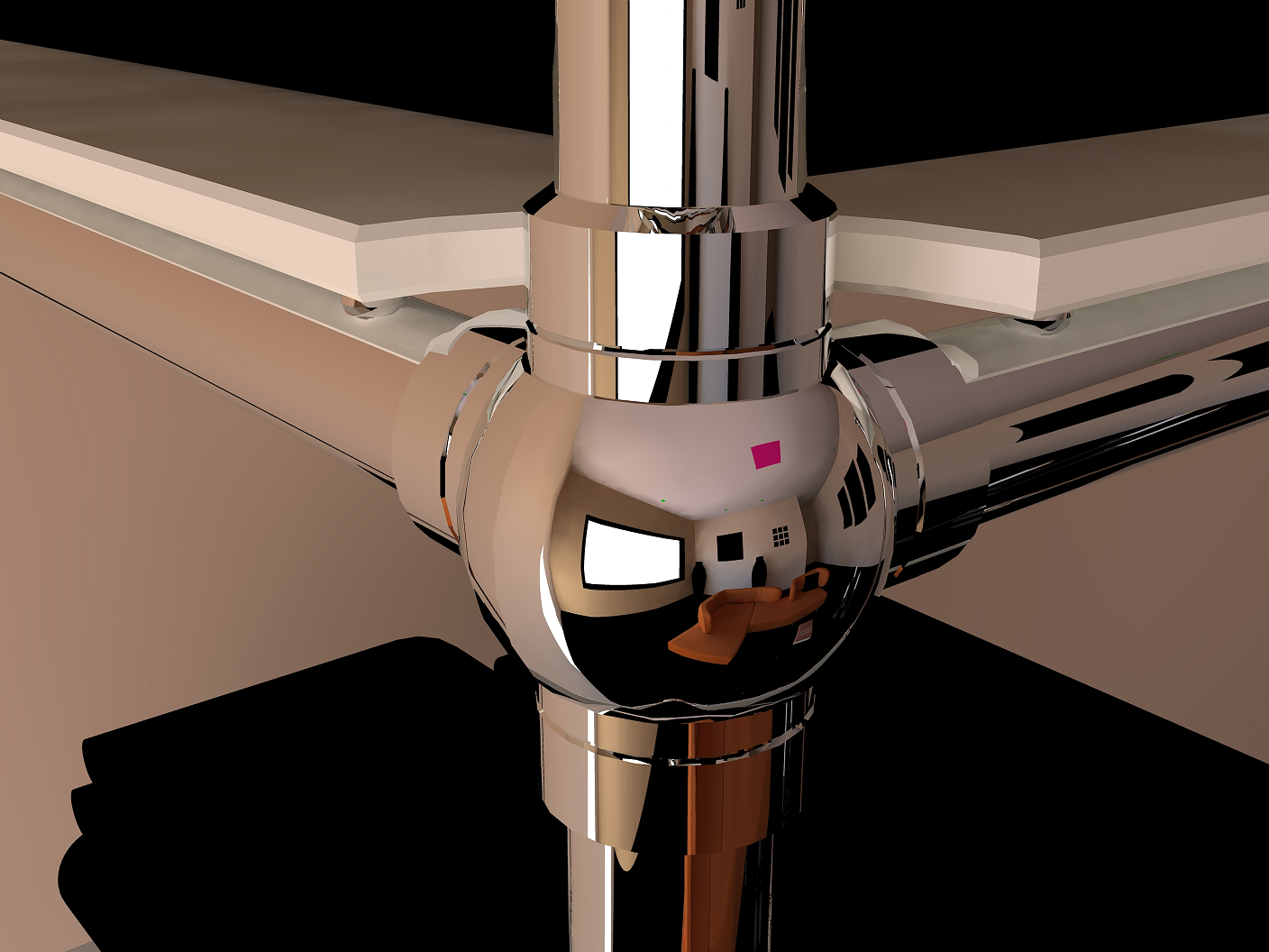
I have attached an image of my results rendered using Kerkythea.
-
Nice work!
-
If you have to assemble the same component more than once you might find it useful to change the location of the component origins to better suit locating them. When you drag a component in from the Components browser you'll have ahold of it at its origin. You can place the origin at a logical point to make it easier to insert. I do this for things like drawer and door pulls to make them easy to place on drawer fronts and doors. You can see that at the end of this and here as well as here.
-
Thanks Dave, I was actually wondering how to set the origin point on components and will definitely check out those resources. I am not sure how these constructions were created in Solidworks and how they will translate to Skectchup, but I assume they are either components or groups or a mix of the two. Is there any way I should restructure these components to better facilitate setting an origin that will be conducive to precise insertion? I plan on using these same components very often and will be creating assemblies with them in specified configurations. I plan on researching "dynamic components' to see if this is a tool I might use creatively to aid with the creation of these assemblies.
-
If the example components you posted were imported from Soildworks, I would be considering redrawing them in SketchUp perhaps from scratch or almost from scratch. It would drive me nuts to have to work with components like those all the time.
As far as restructuring them for setting their origins, first they must be components. As far as doing things to establish where the origins are, I guess that depends upon the components and how you want to insert them. You'll have to figure out what makes sense to you as far as insertion points. The drawer pulls in my examples are easy. It's easy to mark out where the centers of the pulls will go on the furniture. In your case It might possibly be different.
I would suggest that you look at Dynamic Components. You might find they'll do what you need to do. I'm guessing that one of the things you're thinking of making dynamic would be the tubes between the joint pieces. I would handle them differently but you might like that method.
-
I think Dynamic Components are only available in the pro version. I will have to do some more research to learn if it is a viable option to achieve my goals. How would you handle the tubes between the fittings in order to quickly change to specific dimensions? I have made an entire "side" a group and was able to change the width dimension with the move tool. Can components be part of two groups simultaneously (in order to change both the width and depth of an assembly)?
-
Yes, you do need to have the pro version to make Dynamic Components so you'll need to evaluate whether or not that's a good investment for you. It might be if you could use things like LayOut, too. If you are going to be working in fixed increments, the DCs may be the way to go.
If I were doing it I would probably just choose to use the Move tool instead. Most of what I draw is custom, one off things but often I need to be able to edit a drawing to change some dimension(s) It doesn't make any sense to use DCs for those models because of the way resizing works. It's a scaling operation which is the incorrect tool for doing things like changing the length of a rail with tenons on the ends.
One thing I would do for models like the one in the render you showed is to use components only. Actually that's what I do in my own work. Absolutely no use for groups. (The regulars are rolling their eyes over that but in more than 8 years of using SketchUp I've never found a case for my work where a group was desirable over a component.
You can't put a component into more than one group or component at a time but you could make strategic use of components and have a lot of power there. I'll try to make an example for you.
-
There are a few align plugins out there. I never use them so I can't speak to their usefulness, but perhaps one of them would help with simple alignment of the round pieces.
If they don't help, you could also articulate your needs and see if someone could write a simple script to help with it.
Jan Sandström (Pixero) wrote one here:
http://sketchucation.com/forums/viewtopic.php?t=20080And CadFather took his version and gave it a nice looking toolbar here:
http://sketchucation.com/forums/viewtopic.php?t=20233And Didier Burr had also written one:
http://sketchucation.com/forums/viewtopic.php?t=11224Not sure which is best, but I'd start with the one with a toolbar personally.
-
Alright, so this was quick. I just made up the parts out of my head and I did this all between my last post and this one.
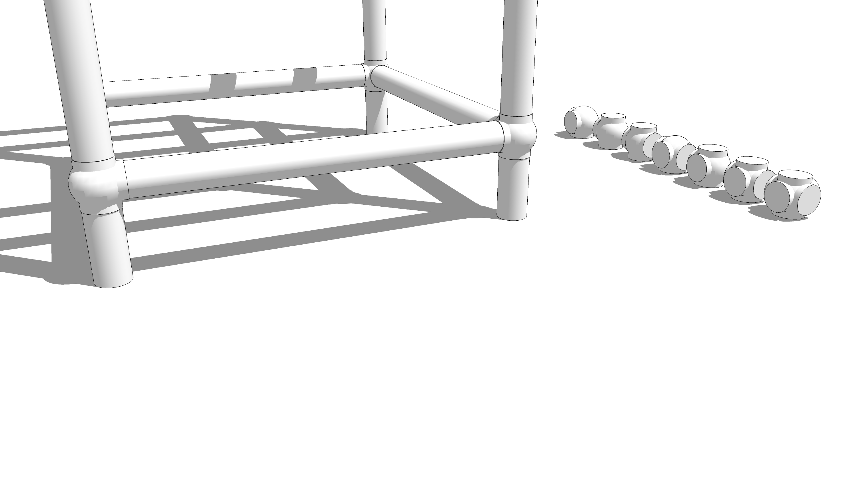
Here are some joint units. Each is a component. I probably missed some combinations, too.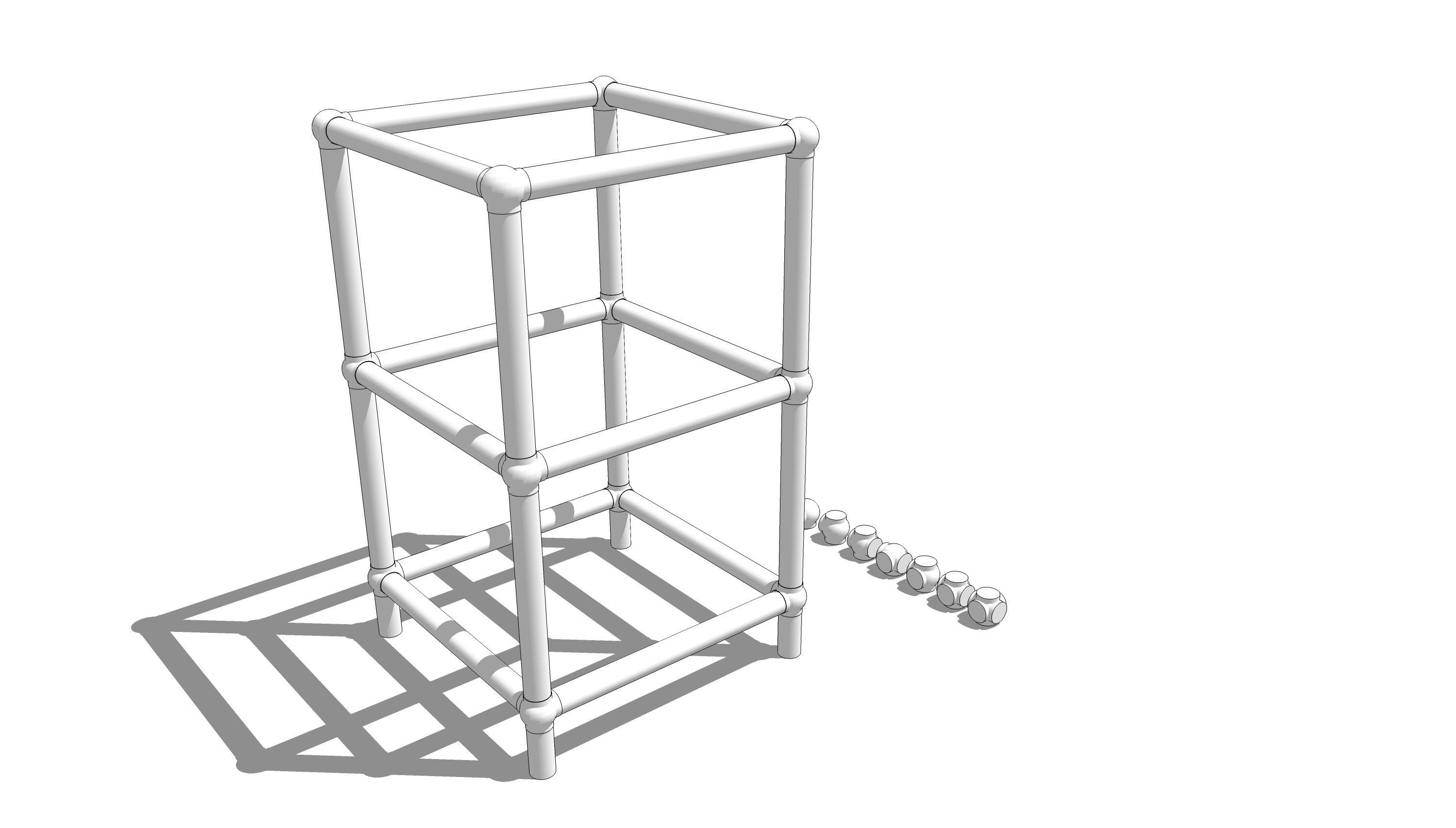
Here's a quick frame. All the tubes are the same except the feet. By the way, the tubes I drew are really cylinders. If you won't see the insides of the tubes there's no reason to have inside walls and the associated file bloat.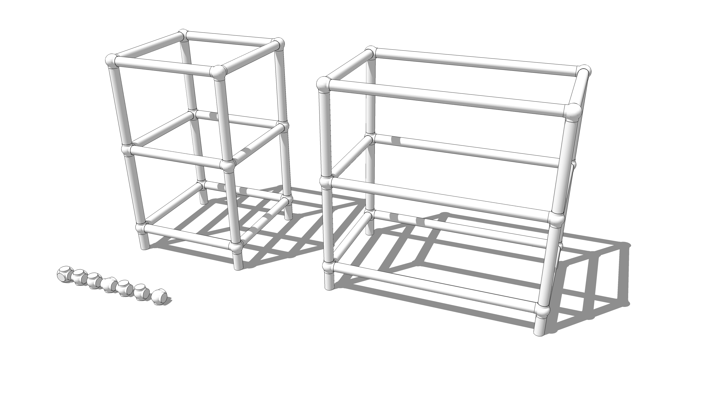
And here I've made a longer version of the frame. I simply moved the right end frame work over 6 inches and then extended the length of the front and back tubes. they are all copies of the same component so I only needed to change the length of one of them to have that carry through.Although the joints are nested components, the frames aren't nested in this case and they were easy to handle, you could do something like make a nested component of an end frame, copy and flip it to make the opposite end. Note flipping is NOT rotating. You won't want to rotate the copy of the end for this sort of thing.
I feel a bit sheepish sending you to another tutorial I did but take a look at this link. there's a video demonstrating how I converted a little fern stand into a hall bench.
By the way, I didn't use any plugins in the making of the example for these images here.
-
Great model there Dave! Well done,
Chris
-
Thank you sir.

-
Thanks Dave, this is really helpful. I will reserve any further questions until I check out all of the recommended tutorials and try to replicate your experiment. I really appreciate the effort.
-
You're welcome. If you want something to play with, here's the model I made. It's quick and dirty.
-
In general the alignment will require a translation and two rotations. You have speciacl case with the way the two axies are aligned ( and their circular symmetry) and where the components axis are place . Slelect the short tube start move and type [0,0,0]. That will move it to the 0,0,0 global axis location installed as Dave shows shows above
Hello! It looks like you're interested in this conversation, but you don't have an account yet.
Getting fed up of having to scroll through the same posts each visit? When you register for an account, you'll always come back to exactly where you were before, and choose to be notified of new replies (either via email, or push notification). You'll also be able to save bookmarks and upvote posts to show your appreciation to other community members.
With your input, this post could be even better 💗
Register Login


Advertisement