Arc deforming ???
-
Try draw an half circle on one of the axes.
'Lift' it in the left ending point by choosing 'Move' and move the left ending point ON THE NORMAL VECTOR ... something like the radius.
The projection of this new 'climbing path' on the 'ground' STILL should be a half circle - but it ain't - why ?
-
You have scaled the diameter, therefore the radius of the bulge has expanded by the same scale factor causing the apparent distortion on the ground plane.
A workaround would be to extrude a semi-circle "solid" and then intersect it with a face at the reuired angle.
-
@arcad-uk said:
You have scaled the diameter, therefore the radius of the bulge has expanded by the same scale factor causing the apparent distortion on the ground plane.
A workaround would be to extrude a semi-circle "solid" and then intersect it with a face at the reuired angle.
"I did not" scale anything
 ) but I'm happy you say a "work around" - because I would say it's an fatal error !
 -
By "moving" one end of the arc you increase the diameter which causes the "scaling" effect.
-
an arc will remain an arc when you do this. (any curve will maintain its shape in this situation)
I guess you're trying to make shape that's no longer an arc??
if so, you'll need to use a different approach.. if you provide more info of what you're trying to achieve, I'm sure a reasonable method will be posted by someone.[edit] it seems like you'd like to make a helix.. is that what you're after?
-
Jeff
When I move the end point along the normal vector I would exspect "it" to move on the surface of the cylinder - and it does ! - BUT the "elastic rope" from the moving end point to the other end point is NOT streching on the surface of the cylinder - it is wrongly floating UP from the surface - and THAT's the error - it should stay on the surface of the cylinder.
I've seen WRONG methods for making a threads using this method - but it SHOULD be "the" method - but the developers implemented the "move" on the arc wrongly !
-
@ksor said:
but it SHOULD be "the" method - but the developers implemented the "move" on the arc wrongly !
i'm not quite sure that you understand what you're asking for..
you want a 'soft move' in which each vertex of the arc moves a different amount vertically in order to deform into a helix..
while i too would like to see something like that in sketchup, i highly doubt it will ever be implemented..your best bet at this point would be to use the CurviShear plugin by Fredo.. it's part of his FredoTools suite.
http://forums.sketchucation.com/viewtopic.php?t=42089
good luck
-
I'm glad you guys know what you are talking about without being aided by pics.
Such would relax the brain into complacency,
or ease it into insight.
-
@brookefox said:
I'm glad you guys know what you are talking about without being aided by pics.
Such would relax the brain into complacency,
or ease it into insight.
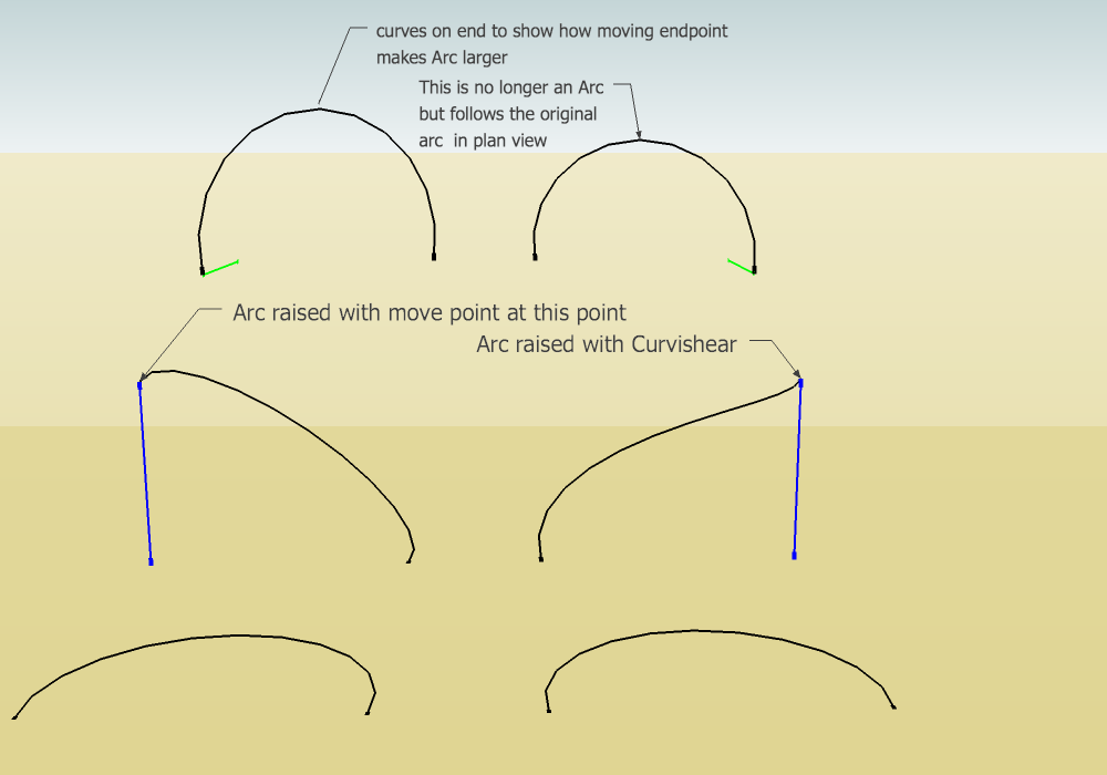
Does this image help? This was talked about in another thread. What is right may be a matter of opinion. The curve with the endpoint moved up is still an arc.
-
Thanks very much, Peter. Very helpful to me. I will come back on the morrow.
Why is the arc with the moved endpoint (row 1 col 2)(which is no longer an arc) no longer an arc? And to be thick, some are no longer arcs, others are (and this is the point?)?
Row 1 col 2 doesn't really follow original in plan, does it, because right the end has been moved (or was that a false horizon?)?
-
@brookefox said:
Thanks very much, Peter. Very helpful to me. I will come back on the morrow.
Why is the arc with the moved endpoint (row 1 col 2)(which is no longer an arc) no longer an arc? And to be thick, some are no longer arcs, others are (and this is the point?)?
The bottom row is the identical arcs lying on the ground plane. The other rows are two views of the two curves:Row two is perspective view of the transformed curves. Top row is the same curves rotated (Note the reference line is green) to see how they look from above.
Moved end point (left side) is STILL an ARC. Curviloft(right side) creates a helix, obviously no longer an arc but it does not deform "IN PLAN" which is the OP complaint about the moved point curve.
@brookefox said:
Row 1 col 2 doesn't really follow original in plan, does it, because right the end has been moved (or was that a false horizon?)?
Ignore the horizon. In Plan here means viewed from above. The top row arcs are set back a little so they may not look the same size, but they are. It was easier to organize that way, sorry

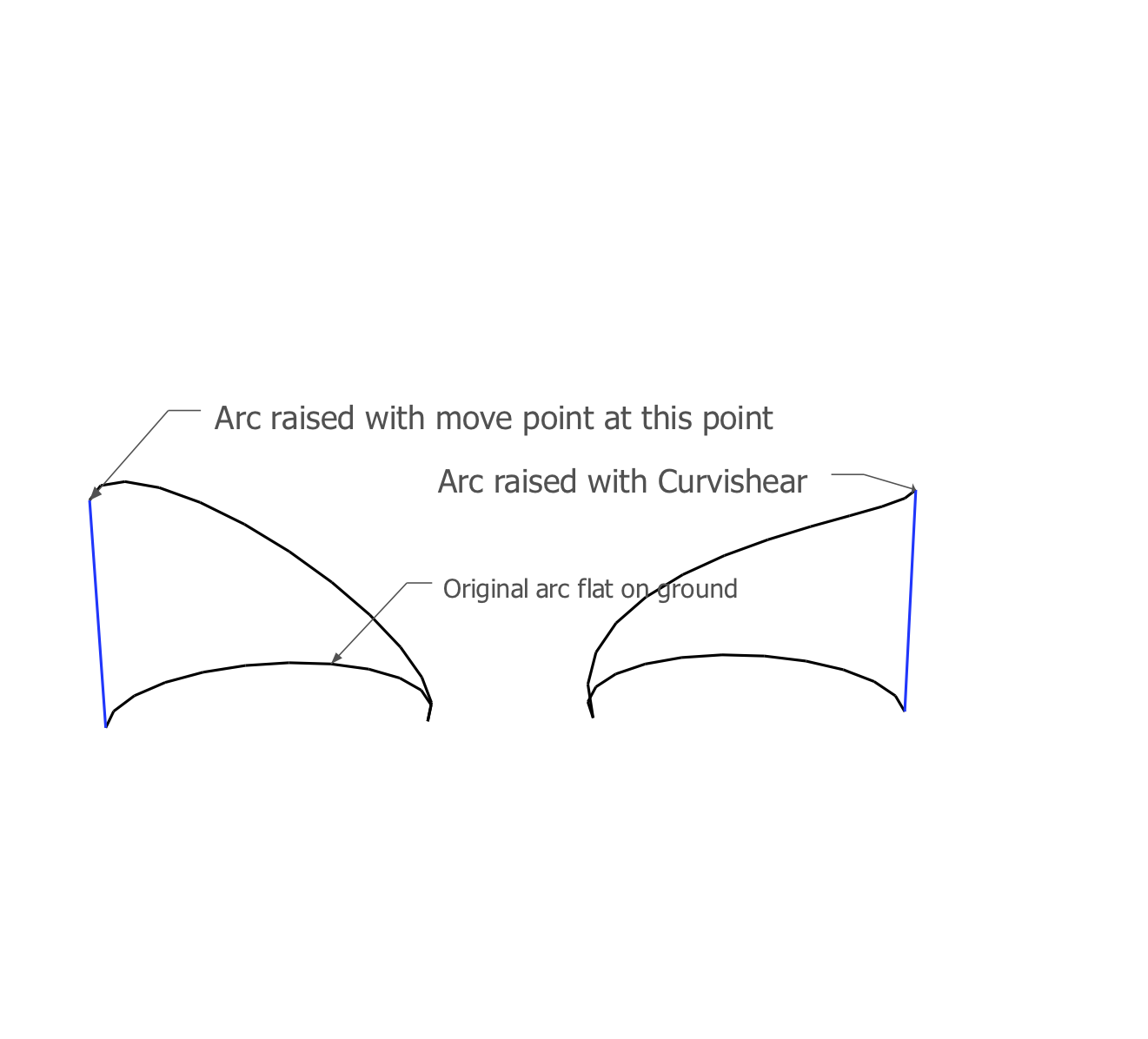
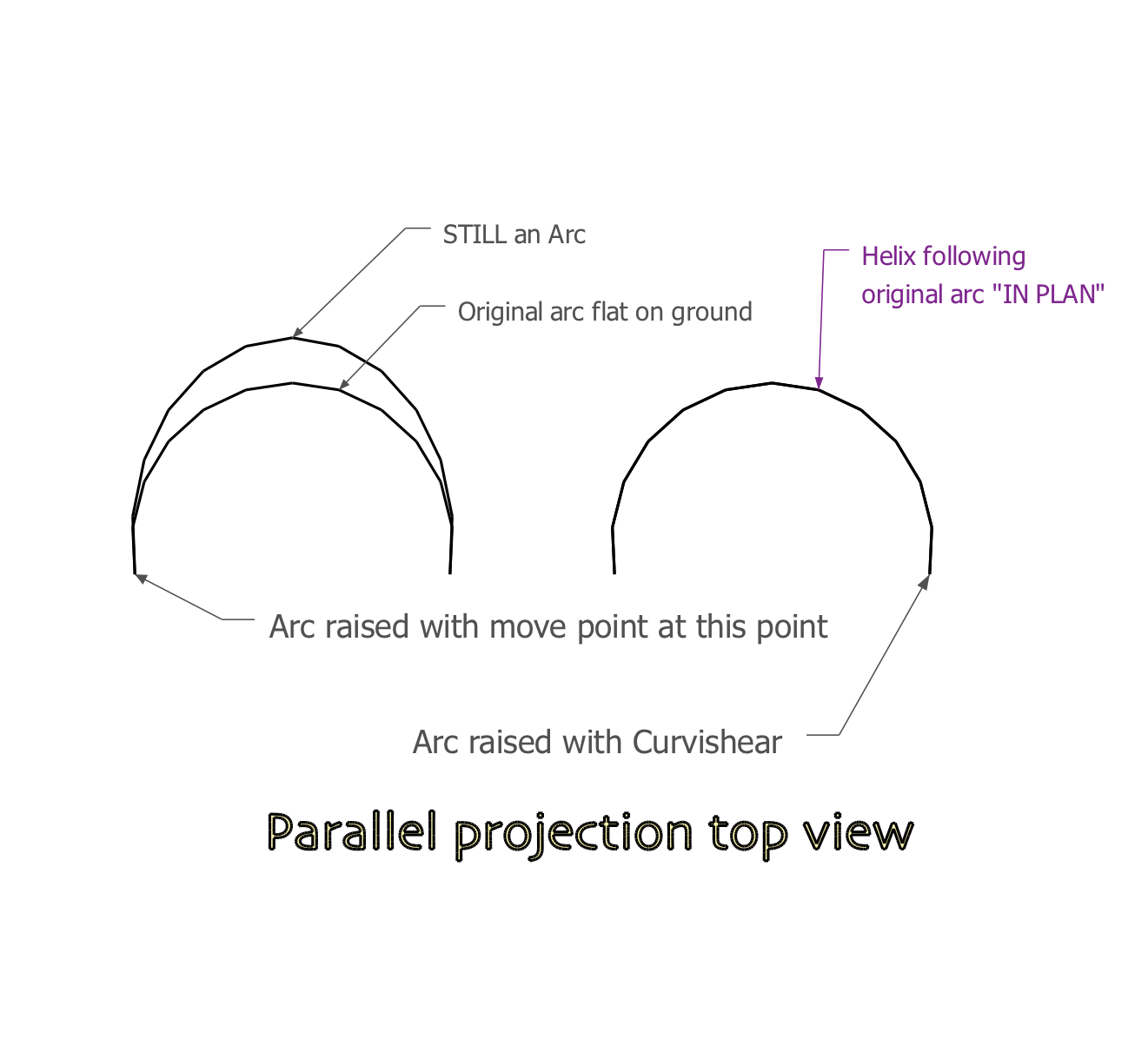
Maybe these pictures (with more words) help. The lower arcs are identical lying on the ground. right above them are the arcs transformed to curves, with the vector blue reference line (same height). The second picture is an orthogonal top view with all four curves still in place.
-
Thanks, again, kind one.
How about (similar to Trevor's suggestion):
- arc
- face it arbitarily
- push pull
- tools on surface: connect two original end points
-
@brookefox said:
Thanks, again, kind one.
How about (similar to Trevor's suggestion):
- arc
- face it arbitarily
- push pull
- tools on surface: connect two original end points
[attachment=0:1d92todr]<!-- ia0 -->scaled arc-1.JPG<!-- ia0 -->[/attachment:1d92todr]
that makes a different shape than what's intended.
for instance, you can't make a spiral staircase (or screw thread) using the shape.. it would be wobbly(?) instead of smooth/continuous. -
Did you catch me cheating?
@unknownuser said:
that makes a different shape than what's intended.
I thought he wanted the plan views before and after to be the same and I thought they are with the method indicated.
@unknownuser said:
Try draw an half circle on one of the axes.... The projection of this new 'climbing path' on the 'ground' STILL should be a half circle - but it ain't - why ?
-
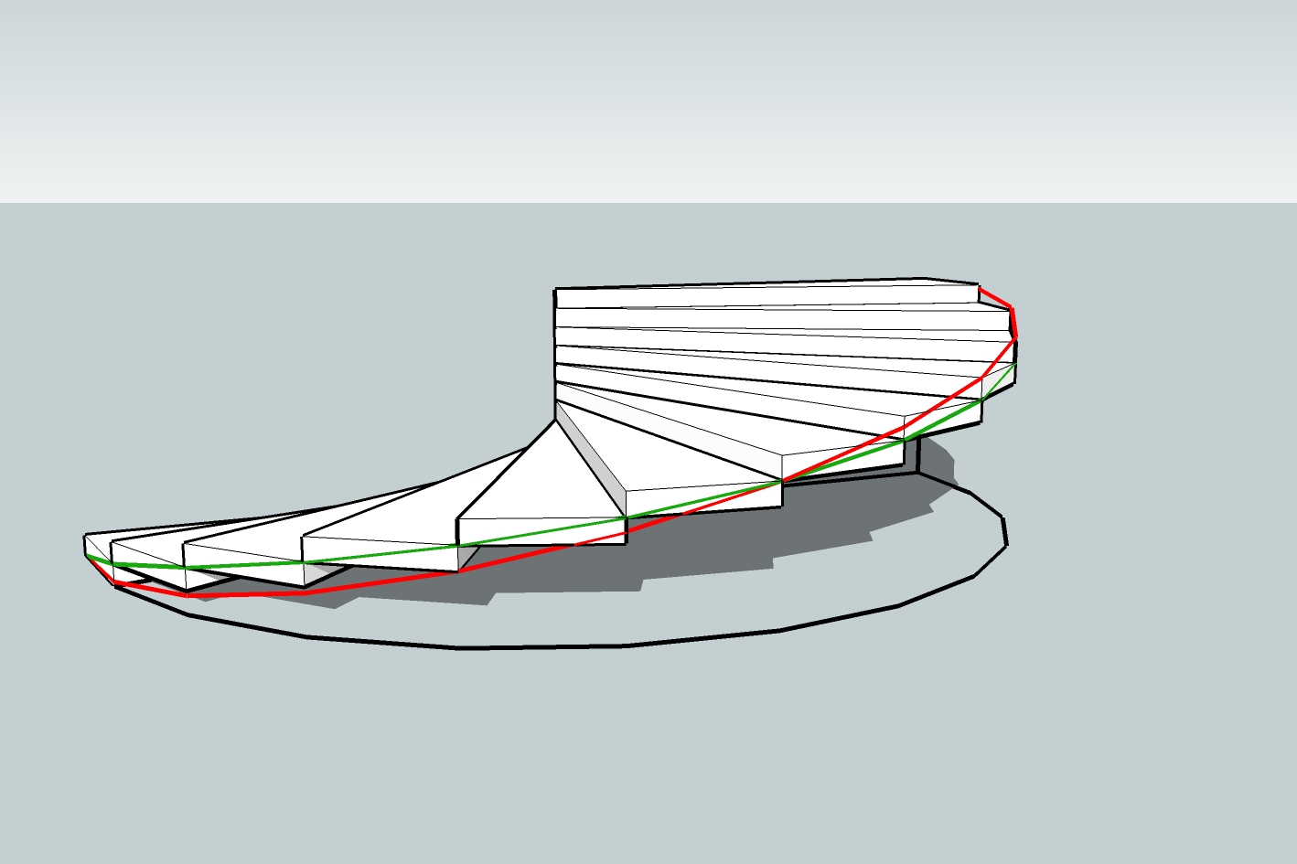
right.. the goal is the green line.. the red line is what happens when a plane intersects a cylinder (ala ArCAD-UK)
edit-
ie.. the green line's slope remains constant (it's a helix).. it goes over 3' / up 6" (which is what those stairs are supposed to be showing )… the red line's slope varies..
from the top, they look identical
-
I see what you are saying, and thanks for showing it, but I didn't think his goal was a helix; I thought he wanted the red line.
I wonder what his purpose wis (was/is).
-
the helix gives the same result you'd expect to see if you did this on a flat surface.. move one end of a rectangle's edge up and it will make a straight line.. as does the helix.
the intersecting a cylinder with a plane will result in some sort of sine curve(?) when flattened out..
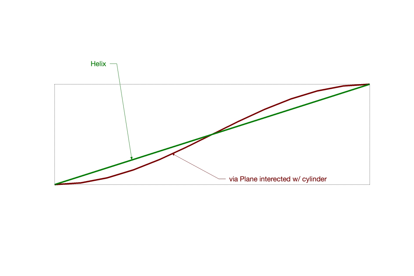
so going off that, i'd assume the helix is the desired outcome ??
(and he's probably trying to make a screw thread as mentioned elsewhere in the thread?)
-
Would someone point me to the original thread, please.
What view is that, Jeff? Seems like a side view of a cylinder cut by a plane is a straight edge, as you show for the helix....oh, you're showing the flattened out view, wherein they are reversed in their flatness, as it were. I guess.
If you could illustrate the flattening out that would cinch it all for a few moments, I feel sure. That's OK; I should accept that as a personal task rather than asking you to model it for me. I'm imagining this is getting stale. Thanks for hanging in.
-
this is the original thread.. the screw was mentioned (indirectly) in the 6th post.
the helix is the simplest (and probably most useful) form out of the two which is why I'm showing it (lots of info left out of the thread so I'm making some assumptions here)
the helix is a straight line that's being wrapped around a cylinder whereas intersecting a plane with a cylinder creates a more complex/compound shape.. it's an S-curve that's then being wrapped around a cylinder.. that's what the two previous drawings by me are supposed to be showing.
I can't make another drawing right now as I'm on a phone. -
Ever heard of Kito Raupp? A master of SU tricks.
[flash=640,360:bdb4kg75]http://www.youtube.com/v/IT5r3AQZBnw[/flash:bdb4kg75]
http://www.youtube.com/watch?v=IT5r3AQZBnw
Advertisement


