[REQ] Import Suspension Construction Points
-
[REQ] Import Suspension Construction Points
I wonder if it's possible to use these two files BTP2013.rar to import construction points or lines to represent the suspension in SketchUp?
if it were, I would buy a plugin that did this, I would also market it in a new 3D simulator that's coming out and an existing simulator that has lots of followers. there are certainly a lot of people in the right places that would be interested.
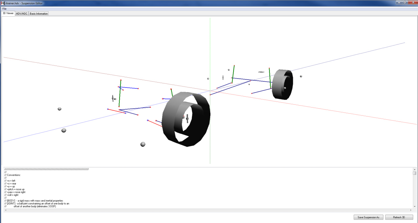
there is already a small program that shows a 3D representation of the suspension. which can be found here. http://www.rfactorcentral.com/detail.cfm?ID=Suspension%20Editor

I would like something like this that used the following files to import this same type of geometry or just construction points into SU. BTP2013.rar
if it could then re-export to these file types after changes, well that would make it that more sellable, but not a deal breaker by any means.
btw the XYZ in these files are different from SU, it's listed at the top of the file.
///////////////////////////////////////////////////////////////////////////// // // Conventions; // // +x = left // +z = rear // +y = up // +pitch = nose up // +yaw = nose right // +roll = right // // [BODY] - a rigid mass with mass and inertial properties // [JOINT] - a ball joint constraining an offset of one body to an // offset of another body (eliminates 3 DOF) // [HINGE] - a constraint restricting the relative rotations of two // bodies to be around a single axis (eliminates 2 DOF). // [BAR] - a constraint holding an offset of one body from an offset of // another body at a fixed distance (eliminates 1 DOF). // [JOINT&HINGE] - both the joint and hinge constraints, forming the // conventional definition of a hinge (eliminates 5 DOF). // ///////////////////////////////////////////////////////////////////////////// -
The .tbc file seem to be 'tires' and has no suspension info...
The .hdv file does mention 'suspension' but I guess it's more about 'behaviors'...
The .pm file contains 'suspension' definition code like this// Front left suspension (2 A-arms + 1 steering arm = 5 links) [BAR] // forward upper arm name=fl_fore_upper posbody=body negbody=fl_spindle pos=( 0.360, 0.126,-1.400) neg=( 0.572, 0.140,-1.325) [BAR] // rearward upper arm posbody=body negbody=fl_spindle pos=( 0.360, 0.126,-1.100) neg=( 0.572, 0.140,-1.325) [BAR] // forward lower arm name=fl_fore_lower posbody=body negbody=fl_spindle pos=( 0.215,-0.120,-1.500) neg=( 0.615,-0.120,-1.350) [BAR] // rearward lower arm posbody=body negbody=fl_spindle pos=( 0.215,-0.120,-1.100) neg=( 0.615,-0.120,-1.350) [BAR] // steering arm (must be named for identification) name=fl_steering posbody=body negbody=fl_spindle pos=( 0.2875, 0.001,-1.440) neg=( 0.570, 0.010,-1.435)so... this is one of four [there are four suspension points] what values do you need to extract out of each set ? forward 'pos' or 'rearward 'pos' [or equivalent 'neg' values] or 'upper' or 'lower'... or both [or all] etc ?
It's quite possible to parse the text in the .pm file and extract values as you desire [what units are the files in and what do you want to use for the cpoints ?]
With some more clarification I can advise how to get cpoints from the settings in the .pm file... -
you're right the tbc is tires... wasn't sure if it got the tire location from that file or not.
hdv is a behaviors...
and the .pm file is the suspension file.
the files are in metric.
there are just these types of joints avaiable.
// [BODY] - a rigid mass with mass and inertial properties
// [JOINT] - a ball joint constraining an offset of one body to an offset of another body (eliminates 3 DOF)
// [HINGE] - a constraint restricting the relative rotations of two bodies to be around a single axis (eliminates 2 DOF).
// [BAR] - a constraint holding an offset of one body from an offset of another body at a fixed distance (eliminates 1 DOF).
// [JOINT&HINGE] - both the joint and hinge constraints, forming the conventional definition of a hinge (eliminates 5 DOF).it would be nice to represent them in some way. other wise just regular construction points would be fine.
the pos/neg thing... is another beast I must learn about. in some places it's obviously position, but then in others it seems to be positive/negative. I'll ask in my simulator forum.
thanks for your attention.
-
Like reading data from an OBJ or DXF file... it would be possible to read the .pm file's data, parse it and add reconstruct 'named elements' in a SKP, that graphically represented what you desire... e.g. component-instances with the right 'length' and xyz values in space etc...
Then any adjusted versions of these could be exported back into an equivalent file format...
It's not exactly clear [yet] what it is you want to read in, and end up with in the SKP

-
if you downloaded the small program that Suspension editor, that's all I want really is the suspension parts in vertex format or bars or lines. with this we build real A arms and Springs and struts and such and this file locates those for us.
-
here is an example.
this is a Ferarri 643 model and it's corresponding .hdv. and .pm files.
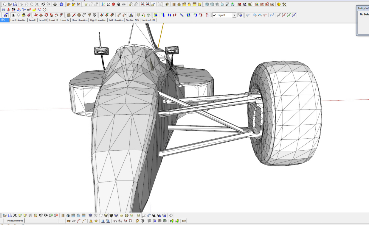
from sketchup

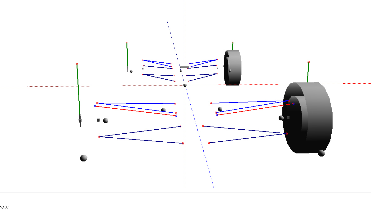
from pm viewer

as you can see the text file is the textual? if that's a word representation of the actual model.
so to import a type of suspension and then build a model around it and maybe change it slightly. and then be able to re-export it would be very helpful. only the lines/bars and certain individual vertex need be exported to the .pm file.
one of these files and some of these measurements have to do with the distance of travel that these components go.
the undertray points or balls are the bottom out of the car and also bumpers or feelers.
also some of these groups/pieces have independent origins.
this is the skp. the .hdv and the .pm
Ferrari hdv,pm and skp
-
here are my questions and the answers so far to them from my other forum.
@unknownuser said:
pos/neg - posbody/negbody in pm file.
could someone explain to me the difference in these and how to know when pos means positive and when it means position?
@unknownuser said:
(Left+/Right-, Up+/Down-, Fore-/Aft+)
"pos="/"neg=" are positions, think of them as points in 3d space.
Posbody/Negbody are links to other references.For all of the bars Posbody=body, Negbody=upright.
The only place this changes is the link from wheel to spindle. For those the Posbody is the wheel, Negbody=upright.
@unknownuser said:
"pos="/"neg=" are positions, think of them as points in 3d space.
so these are two different positions? as in the distance of travel?@unknownuser said:
Pos/neg are the end points of the parts defined by posbody and negbody (end point locations in space of the model)
-
I haven't forgotten about this...

Would it be possible to mark up the 'stick' image to show what is what compared to the .pm file ?
It should be relatively easy to extract the XYS data from each entry in the 'imported' .pm file and make geometry/group in a SKP...
Not so sure about the 'reverse' exporting...
Advertisement


