PVC Piping system
-
Hi all,
I would like to make a library of PVC pipes as used in my country (Denmark) as the producers are very keen on not giving out their models.
I have struggled with the follow me tool for a long time and the rsult is not very good, I would very much like to get som advice on how you would go about making such a model in a few steps. Spigot and "muff" (not sure this is correct) should be seperate groups or components so they can be reused for the many other type of pipes and fittings.
i have attached a 2D dxf as i use for the production of the sorry attempt also attached...Best regards
Jesper -
- seems like attachment is too big...?
please find it here: http://sketchup.google.com/3dwarehouse/details?mid=234cdfb6a2cee7315ab280e3ca9e8914&prevstart=0
-
What sort of difficulty are you having with using Follow Me for drawing this?
I used follow me and the outer curve to draw the elbow (spigot end?) and then a circular path for draw the other end. Notice the profile in the center.
You may find that it is easier to do this sort of work if you scale up by a factor of 10 or 100 so you avoid the tiny face problems. also consider simplifying the model as much as possible. Unless you need to show the inside of the pipe fittings, model only the outside.
Make the parts components and save them into a library for later use.
-
Hi Dave,
Looks good what you have done. I have tried to get the model detailed with the inside shown also, but you are probably right in this case as there is no immediate need to show the inside.
In case I need for future use, how would I get about doing the lbow part with an inner wall, when I try to make an outline and follow-me then it makes strange result like sometimes the curves extend beyound the anticipated end of the pipe?Best regards
Jesper -
Jesper, stick around for a little bit so I can show the setup for the elbow.
-
So the setup for the elbow goes like this. I drew a circle with a 55mm radius centered above the 2D drawing. The red lines show the alignment of the circle over the 2D drawing. It was positioned at the large diameter. The taper is created later. I used the outer edge (the one that disappears behind the circle) on the 2D view as the path for Follow Me. Before running Follow Me, I scaled the model up by a factor of 100. Then I scaled back down when I was finished. To get the taper I used Ctrl+Push/Pull on the end face and pulled it out to align with the end of the pipe. Then I scaled the end face.
If you wanted to create the interior of the pipe, you would offset the edge of the circle in by the wall thickness and delete the center leaving a ring. Run Follow Me as on the circle. The little taper would be created the same way making sure you only scale the outside circle.
-
Hi Dave,
Sorry, I was away for a while. I followed your instructions and all goes very smooth, both ends now done, only a lot of different elbows and then it's time for some Y pieces....

Thank you for your time,
Best regards
Jesper -
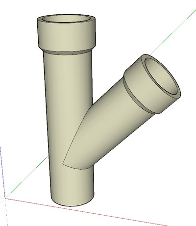
Glad that helped. A Y should be fairly straightforward. Make an elbow with a 45° bend (or whatever the angle is. Then copy the geometry, flip the to make the opposite side and do an intersection. Delete the waste and you're good to go.
I just pulled this one out of my hat. The female fitting is the component made earlier. I probably should have put two copies at the opposite end, though.
-
Looks nice Dave, but I wouldn't think that kind of Y is available for sale?
A One -> Two Y, or upside down Y ?
AFAIK a plumbing Y is usually like this. Probably cheaper to make too?

-
As I said, I just pulled the shape out of my hat. I didn't intend it to match a production Y. The process would be essentially the same anyway.
Advertisement


