Would you like to sit down? EDITED
-
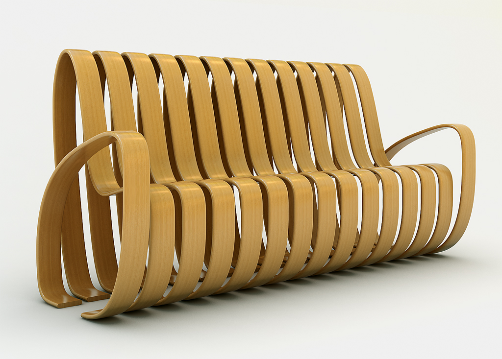
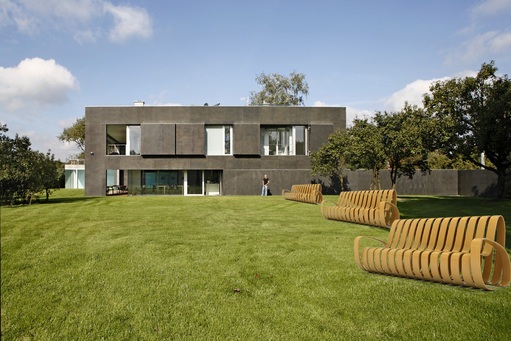
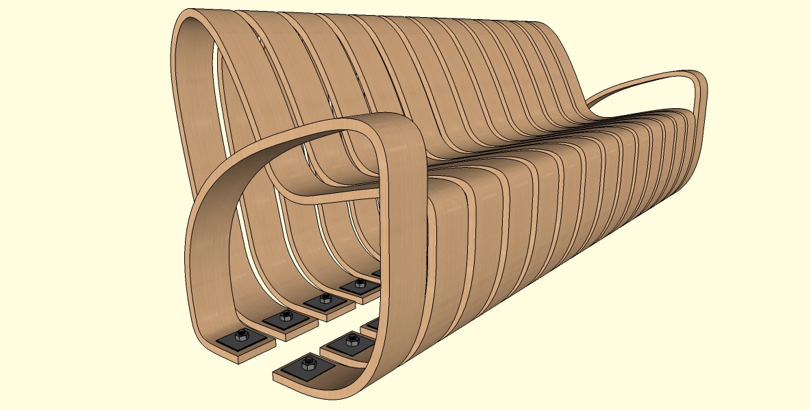
just idea how town bench could look like.

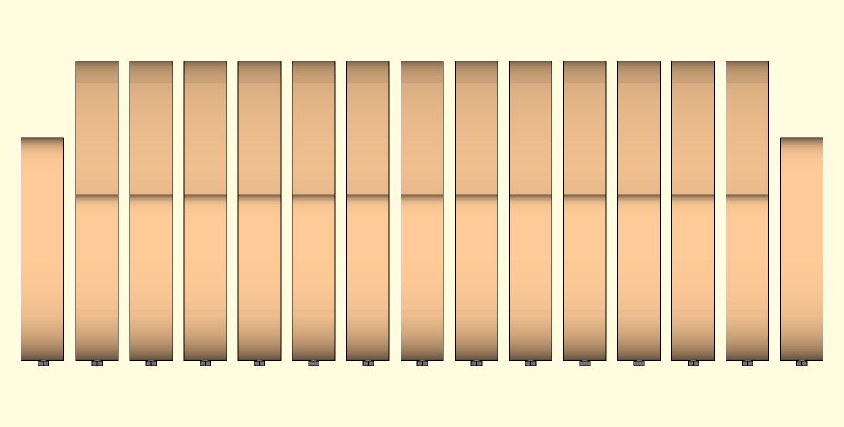
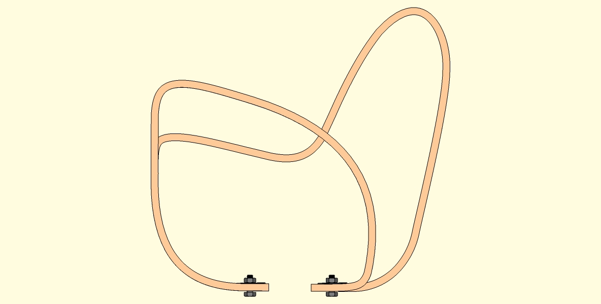
bended wood - beech. single parts are same. every single element screwed to footing. every single element can be separately exchanged or swaped.
(rendered in vray + PS)
cheers
-
every single element screwed to footing<<<
wow that's a lot of screws into the concrete. Also the lateral load on those screw locations would be considerable. IE: if you were to press laterally at the top of one of these bent wood pieces you would create a lever arm with a great distance to the "resistance" all the way at the bottom screws anchored into the concrete. Think about a short wrench trying to undo a nut then using an incredibly long wrench to undo the same nut. The force exerted by using a long lever arm is much greater.
The concept is brilliant but I think you should think about the installation methodology in more detail.
Just my 2 cents.
-
Beautiful concept, but even as a non-engineer/architect, the lateral load problems that Phil mentioned are immediately apparent...like building a 2m high bookcase with no bracing at all at the back.
I would consider adding some kind of sympathetic bracing structure within the form itself. I'd also consider placing some kind of buffer between the elements and the concrete. I could envisage a host of corrosion/rot problems screwing that amount of wood directly into the ground. How about having some kind of substantial wooden or steel 'spine' running along the base...with each element slotted into it? You could still replace them individually, but you wouldn't need nearly as many fastenings into the concrete. -
damn, i cant believe all the screw you used. they look comfortable though! i like your avatar too, cute kitty
-
Why not in only "one ribbon" ?

not sure that will be easy one piece to build in wood
So no need screw or only 2 screws for all this !
-
it's awesome... and beautiful. good work.
-
The concept is quite nice, but maybe I would make each band bigger: make one band equals one seat. That way you have a modular seating system, which needs fewer screws, and you can make a 2/3/4/5 seat variation
-
thank you all very much for your consideration
.@unknownuser said:
every single element screwed to footing<<<
actually, every single element will be fixed by bolt and nut with washer. this is not the place of the system where could occur any problem.
@alan fraser said:
Beautiful concept, but even as a non-engineer/architect, the lateral load problems that Phil mentioned are immediately apparent...like building a 2m high bookcase with no bracing at all at the back.
I would consider adding some kind of sympathetic bracing structure within the form itself. I'd also consider placing some kind of buffer between the elements and the concrete. I could envisage a host of corrosion/rot problems screwing that amount of wood directly into the ground. How about having some kind of substantial wooden or steel 'spine' running along the base...with each element slotted into it? You could still replace them individually, but you wouldn't need nearly as many fastenings into the concrete.it definitely will stay how it is designed.
@unknownuser said:
Why not in only "one ribbon" ?
not sure that will be easy one piece to build in woodSo no need screw or only 2 screws for all this !
it is very good idea, but than it couldn't be made of wood.
@broomstick said:
The concept is quite nice, but maybe I would make each band bigger: make one band equals one seat. That way you have a modular seating system, which needs fewer screws, and you can make a 2/3/4/5 seat variation
i like an idea of modular system for this product, i will consider this idea.
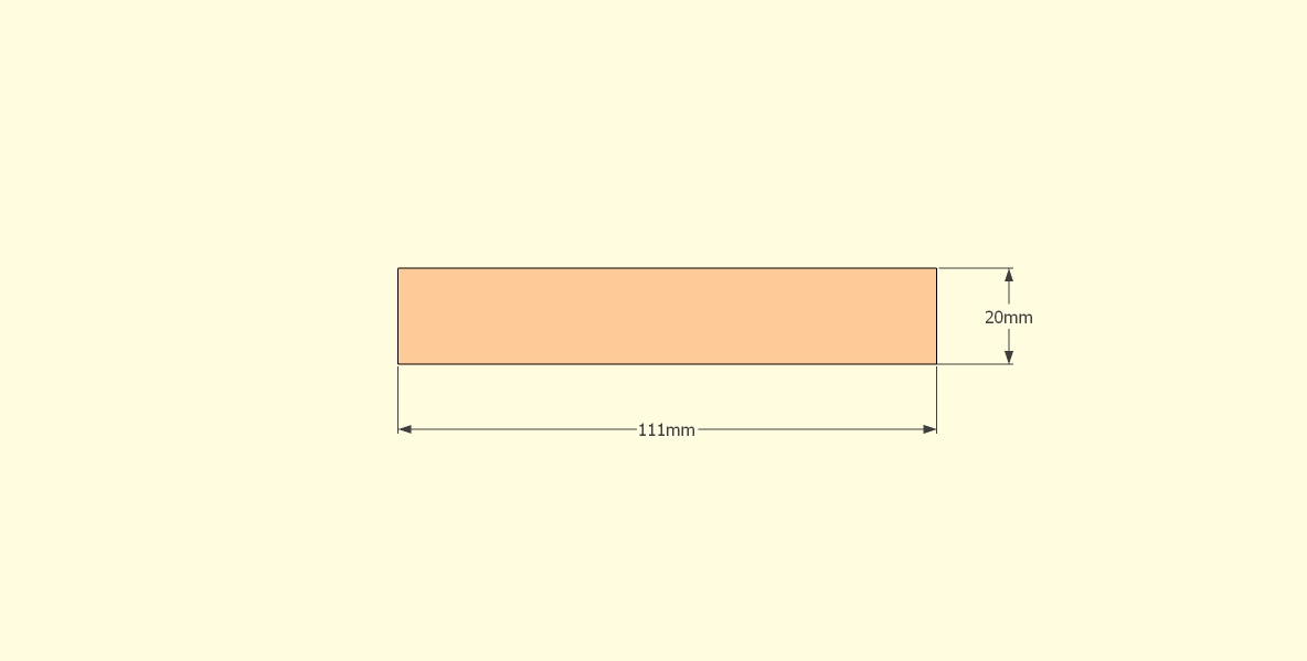
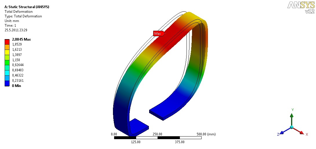
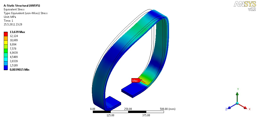
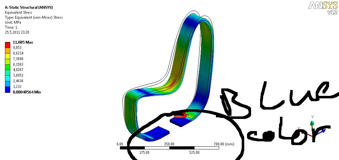
Basic calculation.
modulus of elasticity 13 000 MPa, poisson's ratio 0,49, total force 800N
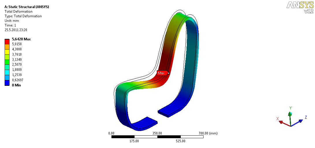
Obr_01.png – deformation after loading (one man)
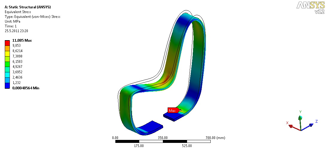
Obr_02.png – reduced stress after loading (one man)
Obr_03.png – deformation after loading (one man)
Obr_04.png – reduced stress after loading (one man)
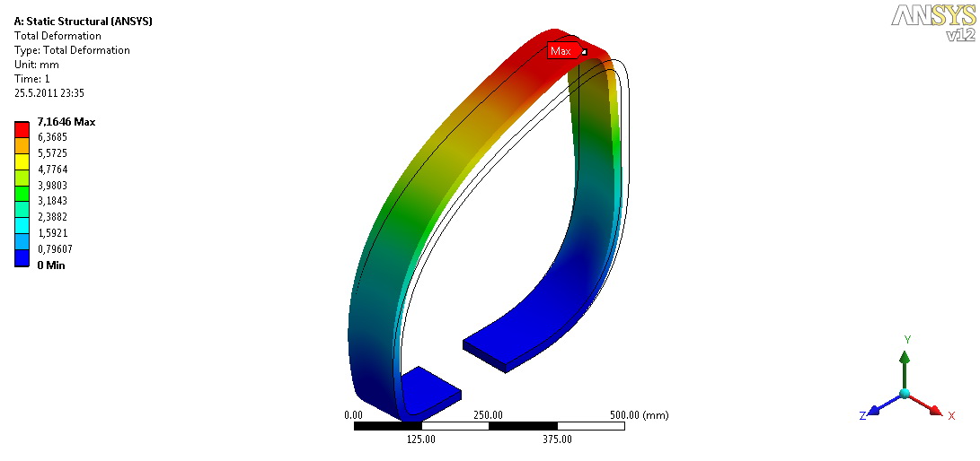
Obr_05.png – deformation after loading (simulation of leaning man)
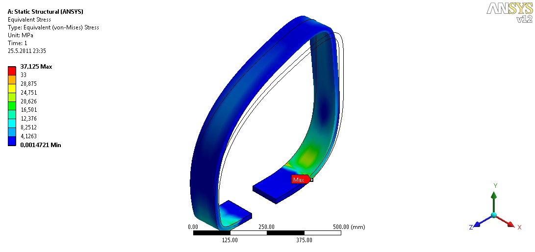
Obr_06.png – reduced stress after (simulation of leaning man)
-
Good to see someone using FEA for structural design. The design suggests that the sections could be clamped front and back as the shapes have flats at the bench to floor interface.
Regards, Bob
-
@jarynzlesa said:
thank you all very much for your consideration
.@unknownuser said:
every single element screwed to footing<<<
actually, every single element will be fixed by bolt and nut with washer. this is not the place of the system where could occur any problem
I'm afraid that's exactly where you will encounter big problems. The problem isn't down/backwards forces, but sideways. With such narrow bands, and no sideways support/bracing of any kind, there will be a lot stress and twisting around those two bolts, and the wood will break very soon. Try with a small cardboard ring and see how very little force it takes to make it fall over sideways when you fix/hold it flat only at the bottom. Making the ribs 25-30cm wide, and fastened with 4 bolts, would help a lot.
Looks nice though -
I have to agree with the others. Very cool design,(very cool) but the lateral forces defeat it. A single connecting cross beam/bar at say, the back curve of the seat bottom, would probably fix that.
-
thank you for consideration.
You can see what happen if you laterally load a rib with force 500N on the picture 5 and 6 (Obr_05 and Obr_06).
cheers . -
Intersting concept - your FEA is also interesting but I suspect that you have missed the point of the comments that have been made. I don't think that the strength of the elements themselves is in question. The issue is very definitely with the fixing. Think about how you can use a claw hammer to lever out nails that are otherwise very strong - something similar to that effect could be a problem for your design.
-
I don't know how those stress programs works, but it looks like everybody else here thinks that the construction will not work very well without any lateral/sideways support.
Like on this little image.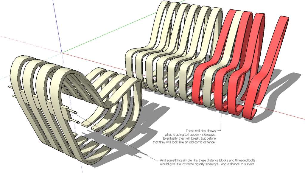
-
Here's an example of a similar concept, the Scandia chair.
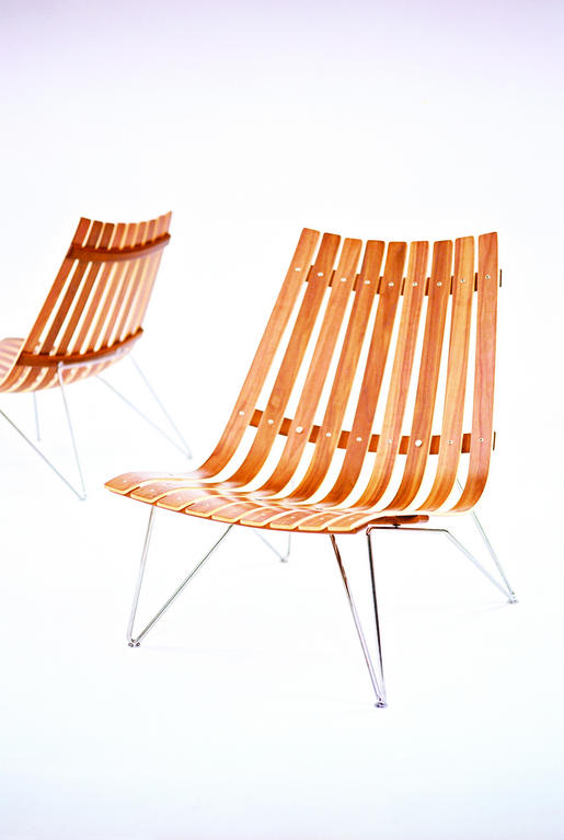
As you can see - lots of lateral support.
-
thank you for comments.
@john.warburton said:
I don't think that the strength of the elements themselves is in question.
it was a question. solved.
@john.warburton said:
The issue is very definitely with the fixing. Think about how you can use a claw hammer to lever out nails that are otherwise very strong - something similar to that effect could be a problem for your design.
this is why i made FEA.
@bjornkn said:
it looks like everybody else here thinks that the construction will not work very well without any lateral/sideways support.
Like on this little image.[attachment=1:2bvrvpb6]<!-- ia1 -->bench.jpg<!-- ia1 -->[/attachment:2bvrvpb6]please, look a little bit closer to ansys outputs and you find out that the situation, you draw with red color, could not happen.
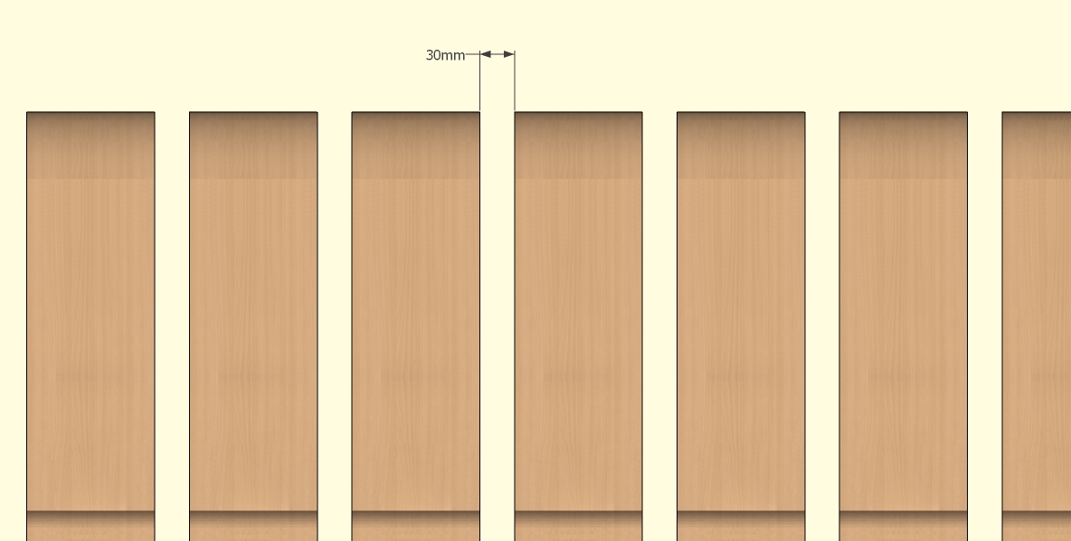
variant with distance block, you draw, would made structure more rigid. but the ribs are supposed to be flexible. distance between ribs is 30mm.@bjornkn said:
Here's an example of a similar concept, the Scandia chair. [img]scandia_lounge_2.jpg[/img]
As you can see - lots of lateral support.scandinavian furniture's design is always inspiring, e.g. peter opsvik's work.
-
@jarynzlesa said:
please, look a little bit closer to ansys outputs and you find out that the situation, you draw with red color, could not happen.
Well, all commments here disagree with Ansys.
Did you tell Ansys that these ribs are fixed with 2 small points/bolts at the ends of the rib, made of laminated wood with fibers mostly following the curve, and that constant flexing/twisting may also eventually lead to water penetrating into the wood around the bolt holes and maybe cause rot?
There are no indicators on the Ansys charts to show where the fixed points are located?
Have you had an engineer or carpenter look at the design? -
here's a little project for you:
- go drill 30 3/4" holes in concrete
- report back with redesign
-
hi,
I do like the design...
having consulted on a number of 'street furniture' contests I'd like to suggest you consider 2 fairly common requirements.
installation time- simply how long will it take to erect on site [minimum being best]
cleaning and maintenance around the 'object' [hosing, sweeping, mowing, etc.]
with these in mind,
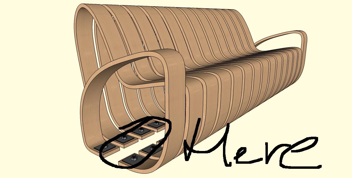
I think you could incorporate a footplate extrusion which allows for pre-construction, rising off the actual substrate and include spacers to alleviate some of the stability concerns raised in this post. The attached image is simply to explain what I mean, not an attempt to hijack your design.
john

-
@bjornkn said:
Did you tell Ansys that these ribs are fixed with 2 small points/bolts at the ends of the rib, made of laminated wood with fibers mostly following the curve
yes of course. without that, the calculation would be completely useless.
@bjornkn said:
and that constant flexing/twisting may also eventually lead to water penetrating into the wood around the bolt holes and maybe cause rot
there is no way how to take into consideration these factors. maybe use some coefficients. calculation is made with perfect material (just like you describe before).
@bjornkn said:
There are no indicators on the Ansys charts to show where the fixed points are located?
@bjornkn said:
Have you had an engineer or carpenter look at the design?
one mechanical engineer and one woodworking engineer.
@driven said:
hi,
I do like the design...
having consulted on a number of 'street furniture' contests I'd like to suggest you consider 2 fairly common requirements.
installation time- simply how long will it take to erect on site [minimum being best]
cleaning and maintenance around the 'object' [hosing, sweeping, mowing, etc.]
with these in mind,
I think you could incorporate a footplate extrusion which allows for pre-construction, rising off the actual substrate and include spacers to alleviate some of the stability concerns raised in this post. The attached image is simply to explain what I mean, not an attempt to hijack your design.
john
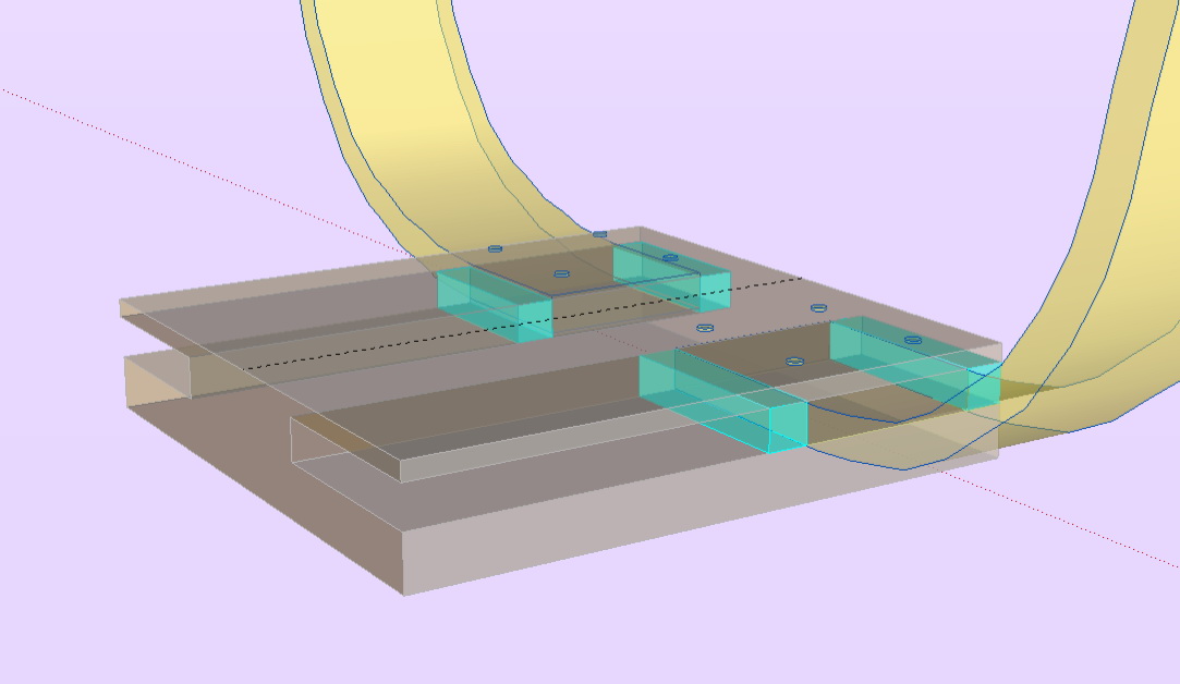
brilliant idea and you are right (installation time, maintenance, lifetime, etc.). thx for pic - one picture say more than a hundred words
.
Hello! It looks like you're interested in this conversation, but you don't have an account yet.
Getting fed up of having to scroll through the same posts each visit? When you register for an account, you'll always come back to exactly where you were before, and choose to be notified of new replies (either via email, or push notification). You'll also be able to save bookmarks and upvote posts to show your appreciation to other community members.
With your input, this post could be even better 💗
Register Login


Advertisement