Face loop vertex order?
-
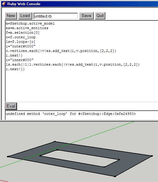
TIG, I got the following error:

Btw, Is there a way to tell if the inner loop is faced or not? How are multiple inner loops vertexes created? -
Did you select the face before running the code?
-
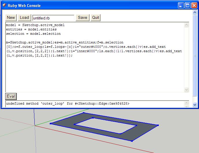
Yes, I ran it in web console. The error message says that the problem is that the outer_loop is not a method for edges, so I tried to do a loop for faces, but failed.
-
From the screenshot it doesn't look like you selected the face.
I just tried the code myself, works fine. -
Hmm.... I'll try again.
-
What could the problem be.....Must be with my system???????

-
In that example you have selected lots of edges.
Select only the face.
-
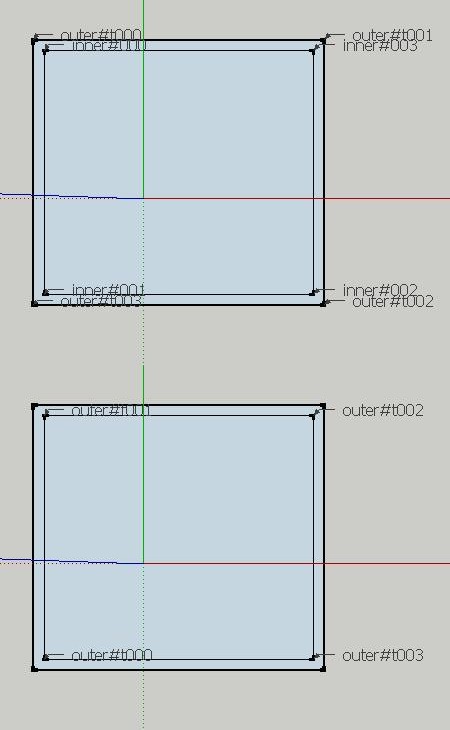
Got it. I was previously selecting everything. Guess I'am not too good at following instructions. The top image is with selection of the outer ring, and the bottom image is that of the center. Btw, I have on-board Intel at home, so OpenGl fails here for me, and face selection isn't clear.
When I draw faces by lines, going clock wise, or counter clockwise creates different sides of a face. but clearly (now to me), that is a situation unrelated to this.
Too bad I can't use this to find holes in faces generated by closed Dxf polyline data.

-
A loop that is ONLY an outer-loop returns its vertices counter-clockwise.
A loop that is an inner-loop only OR that is an outer-loop to one face BUT also formers an inner-loop to another face returns its vertices clockwise - even if it is the outer-loop to a face you are testing - you can of course check for the loop's duplicity and take that into account.
You need two sample DXFs - one with a face+hole and the other the same but with the hole filled - then you could find the difference ?
There are rules about face normal and loop direction for CAD 3D Faces ? Are you following these ?? -
TIG, As you suggest, I will work on this and post what I find. Thanks.
Advertisement


