sketchucation logo sketchucation
    • Login
    ℹ️ Licensed Extensions | FredoBatch, ElevationProfile, FredoSketch, LayOps, MatSim and Pic2Shape will require license from Sept 1st More Info

    [Plugin][$] Curviloft 2.0a - 31 Mar 24 (Loft & Skinning)

    Scheduled Pinned Locked Moved Plugins
    1.3k Posts 297 Posters 2.4m Views 296 Watching
    Loading More Posts
    • Oldest to Newest
    • Newest to Oldest
    • Most Votes
    Reply
    • Reply as topic
    Log in to reply
    This topic has been deleted. Only users with topic management privileges can see it.
    • W Offline
      wfiinch
      last edited by

      Just installed Curviloft into my SU8 and am excited as all hell about the possibilities!

      One question: I need to apply a directional material (wood grain) to the new surface. It applies the pattern to each individual facet, sometimes in the wrong direction. How do I change the pattern direction on a Curviloft surface?

      Okay another question: what exactly is the Sketchup structure of a curviloft surface? Can I explode it?

      Thanks!...and good job on the plugin!

      1 Reply Last reply Reply Quote 0
      • GaieusG Offline
        Gaieus
        last edited by

        It comes in as a group and yes, you can explode it. Turn on hidden geometry (View menu) to se the structure.

        As for texturing it, you need to apply the texture to the surface itself (groups with curved geometry cannot be textured from outside without the texture being applied chaotically). Even on the surface, most probably you need to turn on hidden geometry, apply the texture on one facet; position it then sample and apply on the other facets. Depending on the complexity of the shape, it may take a while - or you can use some UV mapping tool for it.

        Gai...

        1 Reply Last reply Reply Quote 0
        • fredo6F Offline
          fredo6
          last edited by

          By the way, I normally fixed this issue of coplanar contours on the horizontal plane in Curviloft 1.1.

          This was signaled by Pilou with a workaround by Diego-Rodriguez

          Fredo

          1 Reply Last reply Reply Quote 0
          • T Offline
            tulacong
            last edited by

            thank goodluck

            1 Reply Last reply Reply Quote 0
            • EscapeArtistE Offline
              EscapeArtist
              last edited by

              Fredo,

              I don't know if this has already been discussed, but there seems to be an issue with "loft junctions following two paths". I create a shape using bezier curves and then convert them to polyline dividers. The script does a really nice job making the overall shape, the problem is along the seam where the profiles meet. It may be due to a mismatch in the number of segments in the edges from one side to the other, but Curviloft creates extra faces that are "folded" into the geometry and are essentially invisible until one goes in and starts moving verts around. The cause a visible seam to show up when shaded smooth. The only solution I know of is to go through and find each face and reconnect/rebuild each edge and face to remove them. Any suggestions on how to better avoid this extra work? Is it as bug or simply an issue with my modeling?
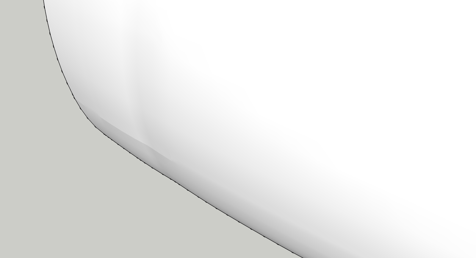
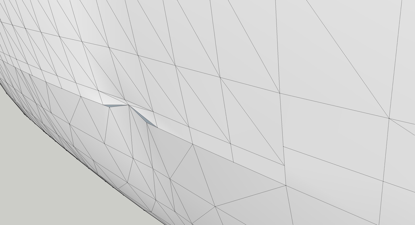
              The seam is visible here
              Grabbing and moving a vertex on the seam reveals reversed faces that are otherwise not visible.

              Thanks for all your hard work!

              1 Reply Last reply Reply Quote 0
              • fredo6F Offline
                fredo6
                last edited by

                @escapeartist said:

                Fredo,

                I don't know if this has already been discussed, but there seems to be an issue with "loft junctions following two paths". I create a shape using bezier curves and then convert them to polyline dividers. The script does a really nice job making the overall shape, the problem is along the seam where the profiles meet. It may be due to a mismatch in the number of segments in the edges from one side to the other, but Curviloft creates extra faces that are "folded" into the geometry and are essentially invisible until one goes in and starts moving verts around. The cause a visible seam to show up when shaded smooth. The only solution I know of is to go through and find each face and reconnect/rebuild each edge and face to remove them. Any suggestions on how to better avoid this extra work? Is it as bug or simply an issue with my modeling?

                Would have the model so that I can have a look.
                This seems strange, but Curviloft algorithms have some shortcuts for performance reasons which may explain a few issues like this one.

                Thanks

                Fredo

                1 Reply Last reply Reply Quote 0
                • mitcorbM Offline
                  mitcorb
                  last edited by

                  @EscapeArtist:
                  That second image looks like rather than "extra" reversed faces, you have pulled the mesh somewhat inside out because additional edges need to be placed. The additional edges would be placed only in order to get additional vertices. Adding edges will avoid seam ripping which is what appears to be happening here.
                  I am just saying this from my experience with detail "knitting" on meshes.
                  Of course, I am probably wrong.. again 😉

                  I take the slow, deliberate approach in my aimless wandering.

                  1 Reply Last reply Reply Quote 0
                  • EscapeArtistE Offline
                    EscapeArtist
                    last edited by

                    @mitcorb said:

                    @EscapeArtist:
                    That second image looks like rather than "extra" reversed faces, you have pulled the mesh somewhat inside out because additional edges need to be placed. The additional edges would be placed only in order to get additional vertices. Adding edges will avoid seam ripping which is what appears to be happening here.
                    I am just saying this from my experience with detail "knitting" on meshes.
                    Of course, I am probably wrong.. again 😉

                    The model is as-is Curviloft output, the pulling was done in order to reveal the extra edges and faces. The face isn't visible until the vert is pulled out of alignment because the edges are so close together as to appear to be a single edge. I did re-stitch the seam and it looks OK but for the slight ripple created by my inability to precisely match the desired curvature by hand.

                    Fredo, the model and curves are attached.


                    example.skp

                    1 Reply Last reply Reply Quote 0
                    • T Offline
                      teoj
                      last edited by

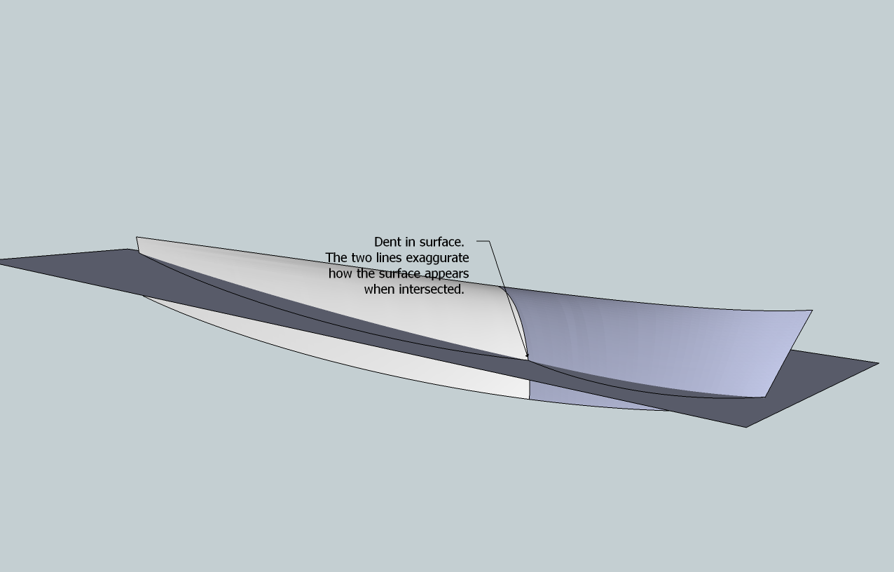
                      Dear Fredo6. I use curviloft extensively (for boat design purposes) and am very grateful for it. But there is an issue that I would like to address: When making hull sides for boats, I create two compound curves. You can see it in the attached images. The upper line is the deck- line, the lower one is the so- called chine. The left side is where the transom is, the right side is the stem. In the middle, there is a line that defines a flare in the bow- sections of the boat. Ideally, Curviloft would create a smooth panel from these lines, but no matter how I do it (skinning, path or lofting), Curviloft seems to do it in a different way than expected, the result being a dented surface.

                      For example, if I selected the middle line first or last, I would expect a different outcome then when it is selected subsequently from left to right or vice versa. Curviloft seems to think of it like two surfaces instead of one, just like the colors indicate. Occasionally the color is the same for the whole panel, but it still appears to be dented.

                      I may be asking too much of Curviloft, but if there is a way that I have not detected yet, then I would appreciate that.

                      PS I have installed latest (January 2011) versions of Curviloft and Libfredo

                      Best regards Teo
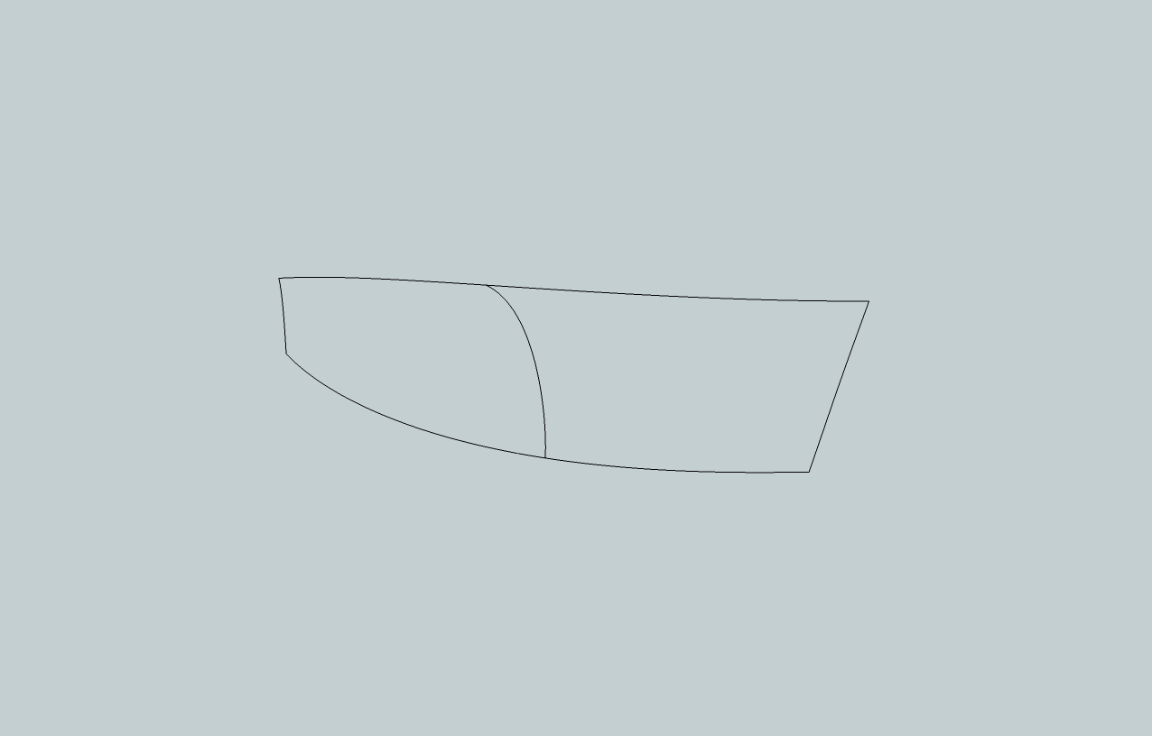

                      Lofting.png


                      Lofting result.png


                      Hull side lines.skp

                      1 Reply Last reply Reply Quote 0
                      • D Offline
                        deanlegg
                        last edited by

                        Hi All
                        Been using this for only a few days and its great
                        Now i'm trying some more tricky shapes with odd results
                        On a simple shape i click on each line and it comes up 1,2,3,4 and skins
                        Then sometimes I click and it comes up 1 with an orange line, next line 1 again and orange and so on. When I click the green tick all the lines turn purple
                        Does this mean its too much for CL?
                        Thanks

                        1 Reply Last reply Reply Quote 0
                        • fredo6F Offline
                          fredo6
                          last edited by

                          @deanlegg said:

                          Hi All
                          Been using this for only a few days and its great
                          Now i'm trying some more tricky shapes with odd results
                          On a simple shape i click on each line and it comes up 1,2,3,4 and skins
                          Then sometimes I click and it comes up 1 with an orange line, next line 1 again and orange and so on. When I click the green tick all the lines turn purple
                          Does this mean its too much for CL?
                          Thanks

                          When contours are contiguous, you need to click in the empty space to separate them. Otherwise all portions are taken as part of the same contour.
                          When contour are not contiguous, then the 'separator' is not necessary.

                          Fredo

                          1 Reply Last reply Reply Quote 0
                          • Whiteowl77W Offline
                            Whiteowl77
                            last edited by

                            I have to say this is one of the Coolest PlugIns I have seen for SketchUp!
                            BRAVO Fredo6 ! ☀

                            I am using CurviLoft 1.1, Loft along Path, and I am creating some geometry that is amazing. It took several tries to get the exact geometry I envisioned. I'll keep working with the Tool.

                            One Problem I am having is when I use the INTERSECT with Model tool to intersect the Fin Top I created with Curviloft with the Dome Shape I created using sketchup followme tool, the Shape I created with Curviloft gets weird (after intersect with selected), and adds extra Lines and distorted geometry. I need to trim the Shape, and then Hide lines, but the geometry gets funky using the intersect process in SketchUp. How do I only select the countor Lines on the END of organic geometry w/o selecting the entire mesh face? I would like to HIDE the Lines/etc. Do I need to use "Tools on Surface" in order to work with created shapes in Curviloft? I'll be painting it soon as well.
                            Basically, I Need to Trim a Shape!

                            I am really digging this Organic Modeling Tool for SketchUp Fredo6
                            Thanks - Andrew Telker
                            http://twitter.com/AndrewTelker


                            Curviloft Created Geometry with Dome - Needs Trimming


                            ![Curviloft Shape Cut - After "Intersection"](/uploads/imported_attachments/nXPq_ConcreteDome_Curviloft_TelkerDesign_Image2.jpg "Curviloft Shape Cut - After "Intersection"")


                            ![Curviloft Shape Cut - Before "Intersection"](/uploads/imported_attachments/wIC9_ConcreteDome_Curviloft_TelkerDesign_Image3.jpg "Curviloft Shape Cut - Before "Intersection"")

                            1 Reply Last reply Reply Quote 0
                            • O Offline
                              on2wong
                              last edited by

                              I really need this plug in!!!!
                              thanks!!!!!

                              1 Reply Last reply Reply Quote 0
                              • O Offline
                                on2wong
                                last edited by

                                That's really help me alot.
                                but how come i cannot install it in my skp?!

                                1 Reply Last reply Reply Quote 0
                                • TIGT Offline
                                  TIG Moderator
                                  last edited by

                                  @on2wong said:

                                  That's really help me alot.
                                  but how come i cannot install it in my skp?!

                                  Read [and understand] the instructions on the download page about what needs downloading [including the Lib stuff that you have to get separately], and then ensure that you put everything in the correct place[s], then activate the tool's Extension and Toolbar etc... Using it's the easy part 😄

                                  TIG

                                  1 Reply Last reply Reply Quote 0
                                  • M Offline
                                    mac1
                                    last edited by

                                    escape artist
                                    Any chance to get the above example loaded to the 3 d ware house so it can be open in SU7.Other wise I have to go dfx and then Su7. Getting these results and would like to see if the conversion is causing problemsSelf intersect faces before removal of duplicate verticesSelf intersect faces after removal of 6983 duplicate vertices

                                    1 Reply Last reply Reply Quote 0
                                    • TIGT Offline
                                      TIG Moderator
                                      last edited by

                                      mac1

                                      I've just made EscapeArtist's example.skp into v7 - try downloading it again from the same post... http://forums.sketchucation.com/viewtopic.php?p=309006#p309006

                                      TIG

                                      1 Reply Last reply Reply Quote 0
                                      • EscapeArtistE Offline
                                        EscapeArtist
                                        last edited by

                                        @tig said:

                                        mac1

                                        I've just made EscapeArtist's example.skp into v7 - try downloading it again from the same post... http://forums.sketchucation.com/viewtopic.php?p=309006#p309006

                                        Thanks.

                                        1 Reply Last reply Reply Quote 0
                                        • M Offline
                                          mac1
                                          last edited by

                                          TIg
                                          Thanks.
                                          As a point of clarification. I am not implying there is any thing wrong with the plugin. I found cases where I have made simple models that show this character and think it is caused by my sloppy approach of applying some of the constraints one must follow when modeling especially when using the follow me tool. I have a feeling if the suggestions made by Fredo are followed this my not show up or its the hand springs I am going through to get the model.
                                          Thanks again

                                          1 Reply Last reply Reply Quote 0
                                          • M Offline
                                            mac1
                                            last edited by

                                            Escape Artist
                                            Some observations ref your model for what they are worth:
                                            1)I was expecting to see the bulk head curve length for what I thought was the keel line to each side to be equal but in most cases there is almost a 2 to 1 difference. Not boat designer, is this normal??
                                            2) At bulk head number 2, counting from stern as #1, this is an obvious kink in the "keel" curve fit just before #2. This IMHO maybe causing some problems. Better tangent here my help??

                                            Still seeing the self intersecting faces in the SU model but only 1( 4 to 5 range before) after the deletion of duplicte vertices which are now 1714 vs 6983 so my hand springs to get from SU8 to SU7 causing some problems.
                                            You may want to run ThomThom,s clean up tool to see if it helps any. That can be done with in SU. It will not give same stats as quoted above. I used TIG's extrude by rails and it gives the same ripple in the surface at the area mentioned above as Fredo's tool does and reason for looking there.
                                            I will be doing more checks and will let you know if I find anything more of interest
                                            Good Luck
                                            UpDate Date 3 Apr

                                            1) Yes I noted shortly after post the model is only portion of Hull;
                                            2) Self intersecting faces traced to dae and /or kmz conversion I do to get into mesh tool. Kmz gives same result but if dae does not have the option of triangulate set then it does also. With it set see only very few and these can be deleted and corrected in SU
                                            3) Attempting to better fit the chine using a cubic spline interpolation did not give any significant changes in surface result

                                            1 Reply Last reply Reply Quote 0
                                            • 1
                                            • 2
                                            • 20
                                            • 21
                                            • 22
                                            • 23
                                            • 24
                                            • 65
                                            • 66
                                            • 22 / 66
                                            • First post
                                              Last post
                                            Buy SketchPlus
                                            Buy SUbD
                                            Buy WrapR
                                            Buy eBook
                                            Buy Modelur
                                            Buy Vertex Tools
                                            Buy SketchCuisine
                                            Buy FormFonts

                                            Advertisement