Help Me Draw A Dome [TUTORIAL]
-
@d0me said:
Firstly, you mention that the angle at the top is now 90 degrees instead of being acute. Would you mind elaborating on you've come to thing conclusion. Sorry, my understanding on architecture jargon is limited to none.
I was always under the impression that a screeder and spinner was the same thing. I was obviously mistaken. Where can I see images of how the 2 work in their own way.
Originally you had six segments meaning the angle at the top of each segment was 60 degrees - an acute angle. Acute angles in concrete are difficult to make because the material runs out to nothing, and are therefore easy to break.
The screeder in flat work would normally be called a rule or straight-edge, which I thought might be confusing as you are working with double curves. The spinner is just a device that rotates the rule or "curved edge."
But anyway I think what I suggested in my previous post should really give a very good chance to do a good job. Let me know it any part is unclear.
And yes I agree photos are a must!
-
D0me, you may find this Sunday idea the basis for a good solution.
See also sketch .skp
-
Hi Chris
With regards to the spinner, I'm still curious to know what sort of contraption can be made to fit on my wood and the pipe (2" Diameter)?
This contraption should be able to stay in a stationary point on the pipe and spin.
I've thought up a few ideas but had to disgard them because if I have a contraption that will be tightened in place and at the specific height on the pipe, it won't spin if you know what I mean. And if I leave it loose it won't stay at the height on the pipe I wish for it to stay.
Any ideas?
Thanks
Regards
D0me -
Basically you need two pipes one fitting inside the other like a telescopic leg. One has the wood clamped to it and rotates; the other needs to be solidly fixed to keep vertical. The size will depend on what you can find that will work.
-
Trying to improve my analytical Sketchupping:

-
One plus one ...
-
Hi Chris
Nice sketching
Can you upload the skp of those images? Would love to get a better view of things.
Guys, I'm also starting to redo the model but I am going to use the advice Gaieus gave and start with the pipe first.
Any tips on how I should go about doing so, like e.g the domes first then pipe or the other way around???Thanks
Regards
D0me -
-
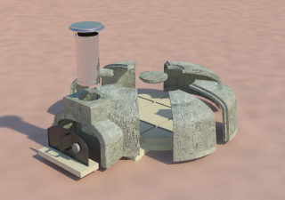
Hey D0me I just came across this:
Have you seen it before?
See the bung, the simple floor, the position of the smoke vent ...
-
Hi Chris
Nice find. Thanks for the link.
Thanks exactly what I am looking to do. One difference is I will pour in my cement to fill the bunghole rather than how they have done it by having the keystone already made.Thanks
-
Hi Gaieus
I'm starting to redo my model and was wondering if you have any tips on how to implement my pipe into the model.
Thanks
-
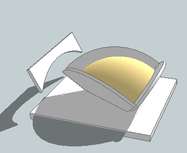
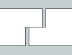
Did you notice the rebated joints?
You don't want to cast each segment on its back (sketch 1) and then stand it up to demould (sketch 2)?
-
@d0me said:
Hi Gaieus
I'm starting to redo my model and was wondering if you have any tips on how to implement my pipe into the model.
Thanks
Which pipe in this case? The one in the middle you will build the dome around?
-
Hi Gaieus
Yes, the middle pipe around which the dome will be built.
-
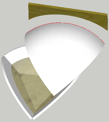
I think I should try and clear up any confusion here.
I suggested spinning a screeder around a pipe to realise the job of the
follow metool when you have a point for the apex of the d0me and a circle on the brick base. The curved rule replaces the profile that is extruded. This works fine when there is no obstruction.When you compartmentalise a segment the form sides get in the way, but the sides do provide the opportunity to draw reference curves not very far apart. You can still use a curved rule and get sufficently accurate substrate layers. Most important the last layer will be most accurate using the other curved rule in the opposite direction.
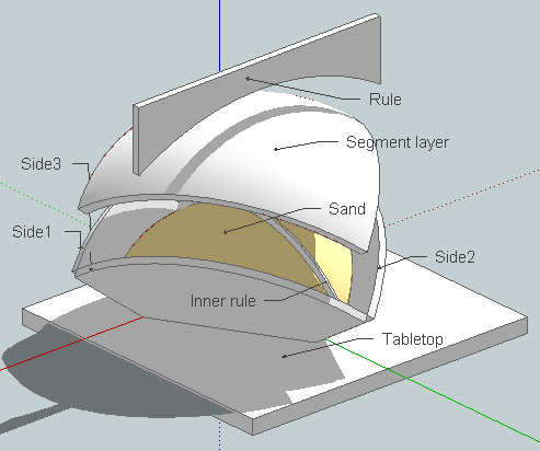
Revised skp showing the inner rule attached.
-
Hi
Chris, should there be any concern or precautions taken should I still choose to leave a bunghole and fill it later. I will require a pipe in my center to help create the bunghole?
Gaieus, I completely forgot about looking through the attachment you posted when i requested how to print my model to scale. Thanks for showing me the steps. That is exactly the way i pictured it my head. Now, just for me to add my pipe and then redo the model, print it to scale and get this "Baby" started.
Look forward to hearing from you guys
Regards
D0me -
@d0me said:
Chris, should there be any concern or precautions taken should I still choose to leave a bunghole and fill it later. I will require a pipe in my center to help create the bunghole?
Just cut a piece out of a plastic pipe if you want a round bunghole or plywood if square; wedge either into top of form. Remember to set on the splay to create a bevel; or form a rebate. But it is really not necessary now you have only four pieces.
Good luck!
-
@d0me said:
Hi Gaieus
I'm starting to redo my model and was wondering if you have any tips on how to implement my pipe into the model.
Thanks
So how thick this pipe would be?
-
Hi Gaieus
The pipe is 2" diameter and about 5mm Thick.
Thanks
-
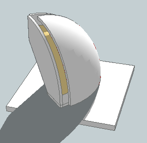
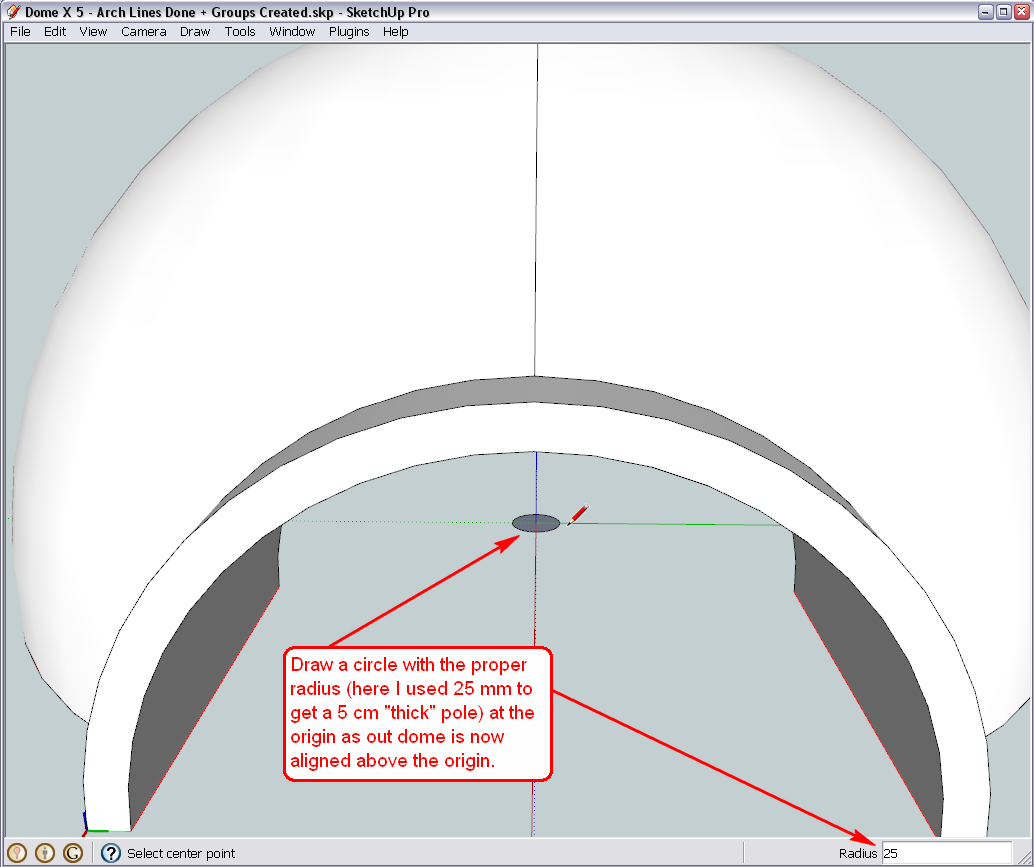
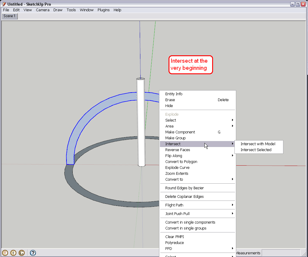
OK, although 2" is not exactly 5 cm (I guess you meant centimetres, not millimetres?) here is the way with our existing domes - although best would be to do this either before we make some of the pieces unique (for the entrance) or to do the whole thing with the hole applied as shown in method 2 later below.
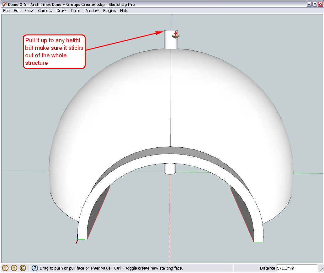
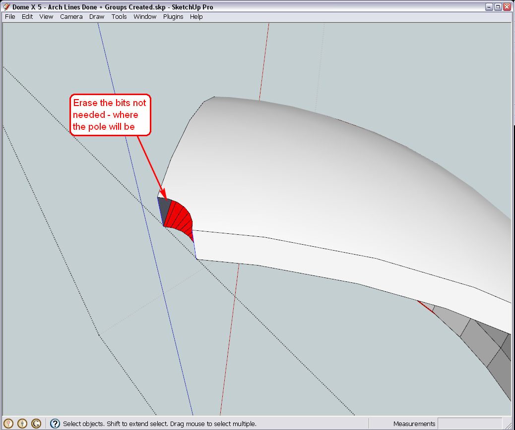
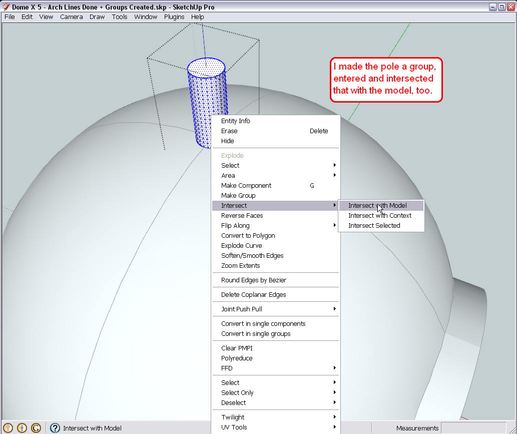
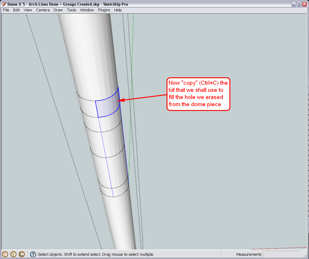
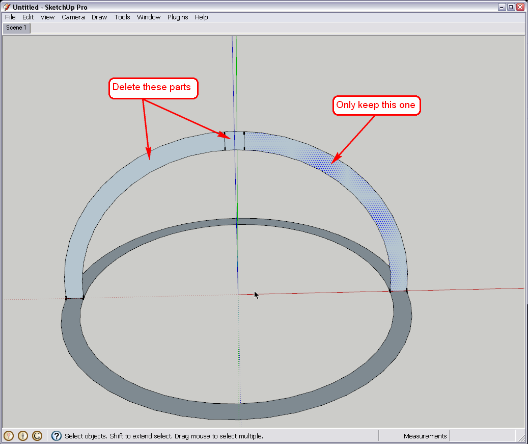
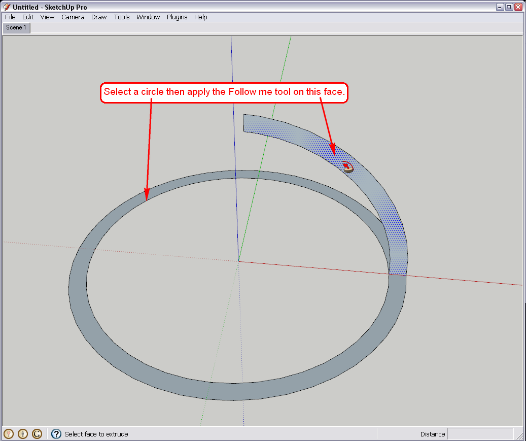
So method 1 is very similar in theory to how we made the entrance. You need to pull that pipe up, intersect the pieces as well as the pipe itself, delete unnecessary geometry and insert bits copied from the pipe back to "heal" the hollows.
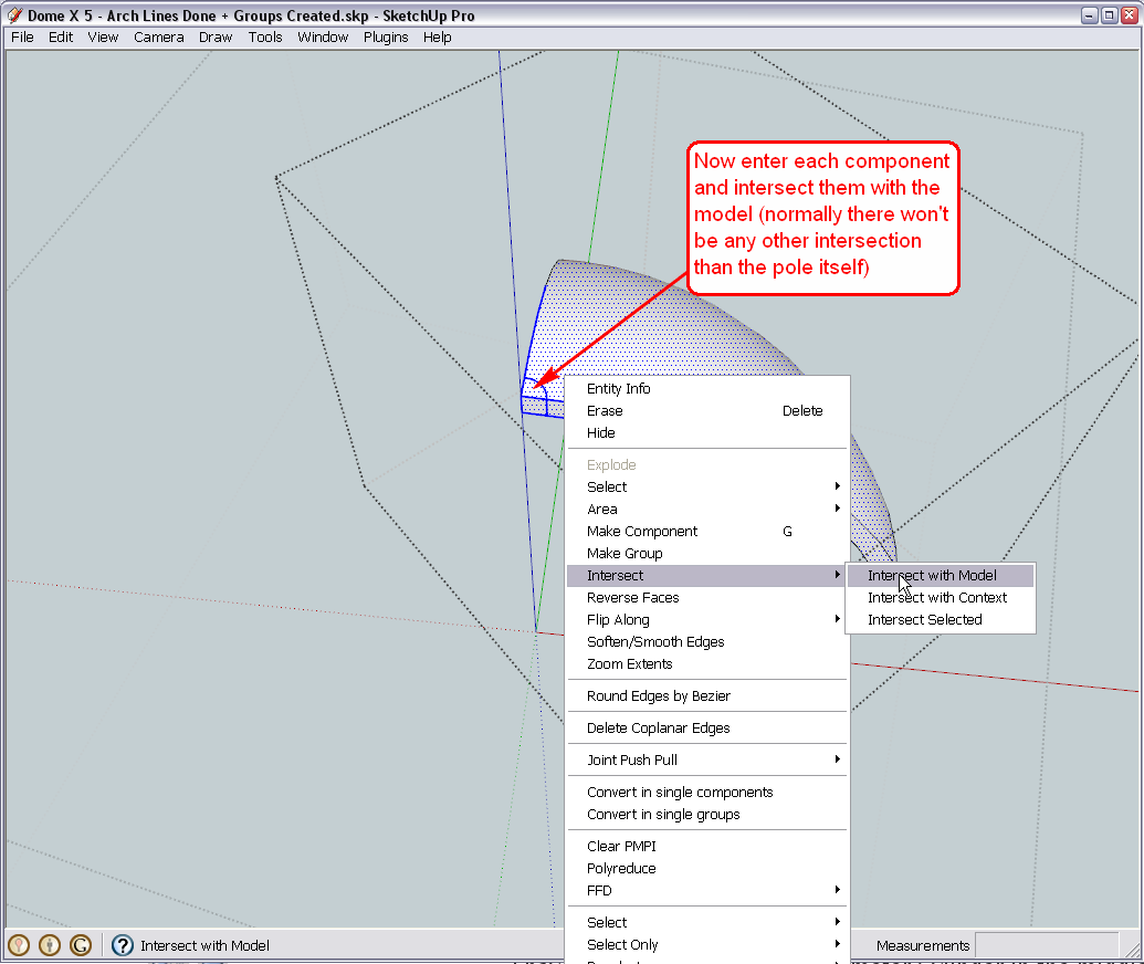
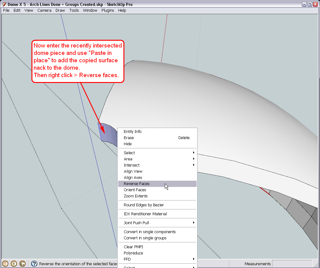
It is obviously a tedious process. If you did it before making some of the dome pieces unique (for the entrance), you could halve the pieces needed be intersected and to insert back as when you do that with one component, all the other instances change, too.If you restarted your project, you could already include the pipe hole into the domes as per this second method:
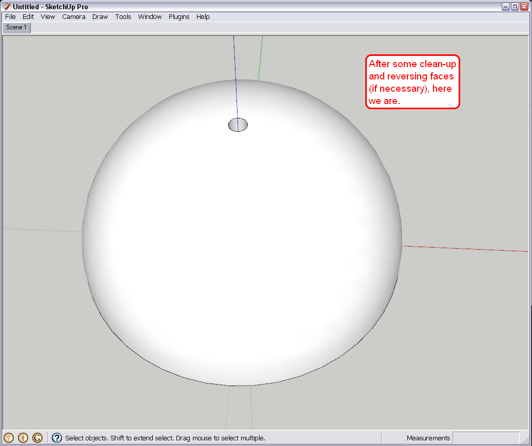
Of course, here it is demonstrated with one dome only - do the same with each.
Hello! It looks like you're interested in this conversation, but you don't have an account yet.
Getting fed up of having to scroll through the same posts each visit? When you register for an account, you'll always come back to exactly where you were before, and choose to be notified of new replies (either via email, or push notification). You'll also be able to save bookmarks and upvote posts to show your appreciation to other community members.
With your input, this post could be even better 💗
Register Login


Advertisement