Help Me Draw A Dome [TUTORIAL]
-
Hi Gai
I’ve gone quite far but a few questions and minor problems arose and are discussed below.
While following the tutorial, I came across a post where you said my dome is upside down. How do I check if I’ve made this mistake again or not?
After continuing further, I came across this image where you mentioned some extra line segments and to delete them but I can’t seem to find them on my current model. Are the segments there somewhere and I am just missing it?
After creating my slicing plane, I positioned my rotate tool on the slicing plane till I got the inference (Intersection in Group (Rotate Tool Is Green)) and then I dragged the tool up until I got an inference saying “On Blue”. I then grabbed the corner of my slicing plane and moved it to the nearest midpoint. It did snap to the Midpoint but the inference I got was End Point though I could physically see my slicing plane on the midpoint. Is this anything to worry about?
You mentioned here that you temporarily Grouped Everything, do I did the same by selecting everything and right click > make group.
Now I am at this image . This is what I’ve done so far. I double click my dome which still has everything grouped except the newly created arch entrance (At this stage, I’d like to ask whether all the pieces of my dome should still be grouped as you mentioned here that it is a temp grouping). Once I enter the editing context of the group, I triple clicked the left dome piece to get inside of the geometry. I then right clicked and selected intersect with model. After doing this, I used Ctrl+H to hide the rest of my model but now my dome doesn’t look like yours found in this image .
I have a backup before intersecting the model and I may have a backup before the temporary grouping if we need to go back a few steps.Thanks
Regards
D0me
-
Well, I also noticed that for some weird reason (and no, I do not know or understand the reason) when I group those circles, they get exploded. Not a big deal because the follow me tool would explode them anyway. There is that inconvenient issue only that in order to establish the path for the follow me tool, you need to select the segments individually - unless you think a little bit.

After thinking, select everything by triple clicking then deselect the arch face and its bounding edges by holding the Shift key and double clicking on it. Now you have the circle selected only - pick the follow me tool and apply it on the arch face.@d0me said:
After continuing further, I came across this image where you mentioned some extra line segments and to delete them but I can’t seem to find them on my current model. Are the segments there somewhere and I am just missing it?
I cannot really remember where those segments came from - but if they are not there now, no problem at all.
@d0me said:
After creating my slicing plane, I positioned my rotate tool on the slicing plane till I got the inference (Intersection in Group (Rotate Tool Is Green)) and then I dragged the tool up until I got an inference saying “On Blue”. I then grabbed the corner of my slicing plane and moved it to the nearest midpoint. It did snap to the Midpoint but the inference I got was End Point though I could physically see my slicing plane on the midpoint. Is this anything to worry about?
I don't know why it says endpoint but if you are sure it is not an endpoint, it's okay then. Maybe there is a broken line somewhere but it won't cause any serious problem I believe.
@d0me said:
At this stage, I’d like to ask whether all the pieces of my dome should still be grouped as you mentioned here that it is a temp grouping
I only grouped those things because it is easier to handle the pieces together when rotating. In fact, that grouping is not necessary at all - I only did it because as a lesser experienced user, you may not be able to do the rotation at once perfectly and this way we could avoid re-selecting the pieces all the time. If you now feel comfortable with the tools already, no need to group at all - and you can explode this container group when you are done.
At the first sight, your dome looks just fine except for one thing; all faces are inside out. Select the faces (inside the components), right click and "reverse faces" so that the white faces are outside. It is not extremely important for you but you will need to get used to model everything consistently as who knows when you decide to render your models or export to 3rd party software where this may be important.
Since those are two, identical instances of the same component definition, the "Hide rest of model" command will not hide the other instance. There is another command; "Hide similar" and if I remember correctly, we have also set up a shortcut for you - Shift+Ctrl+H but if not, you can still do it (or don't care about the other instance if it is not too much in your way).
-
Hi Gai
Thanks for the clarifying for me the points in my previous post.
I exploded the group of Dome Pieces and now I am able to access each piece individually without entering a group. I indirectly learned about the Explode Function.@unknownuser said:
(or don't care about the other instance if it is not too much in your way)
I don't really care about the other instance as it doesn't come in the way though I will start making use of that function of hiding similar.
Now comes a small problem
I've managed to intersect the entrance and clean whatever is not required.
Now I am at a stage where I need to close of the face of the entrance but every time I draw a line from 1 end point to the other, it doesn't close the face. Please assist me.Thanks
Regards
D0me
-
Hi D0me,
Whatever you attached does not seem to be the model you put the image if in. In your model, tha entrance piece is one group while in the picture, it is something of two, different groups/components.
So I cannot advise on the model but tried to comment on the image. Of course, you cannot close a face with any entity that is outside of the editing context you are in (i.e. you are working with half of the entrance- how do you expect to close a face with the other half???)
So just draw the half - with two edges (like I depict below). Then you can hide the connecting seam with the Shift+Eraser tool if you want...
-
Hi Gai
I don’t know how I went about uploading the wrong model. Apologies for that, I have so many backups, that I may have incorrectly sent the wrong one.
@unknownuser said:
So I cannot advise on the model but tried to comment on the image. Of course, you cannot close a face with any entity that is outside of the editing context you are in (i.e. you are working with half of the entrance- how do you expect to close a face with the other half???)
I didn’t realize I was outside the editing context of the entity I wish to close the face of. Did I go wrong along the way that has caused this?
I tried to follow your instructions from the image whereby you advised to close the face using lines and then use the eraser tool to delete the seams. I failed to succeed.
So I decided to take a few steps back. I have a backup of my model where the individual dome pieces were still grouped. I left it that way as and didn’t explode the group like how I have done previously.
I then created the first part of my arch entrance.
After that, I used the offset tool to create the second part (3") of my arch entrance. I then interestected my entrance and then cleaned up what was required. Now I am again at the stage where I cannot close the face. I’ve attached the model and this time I made sure to double check it is the same one as the images I have uploaded. Can you guide me using the model I uploaded?
Thanks for being patient with me. Much appreciated
Regards
D0me
-
Well, the intersect command will not generate those faces of course. There are two ways to get them there;
1 - you can "hand-stitch" the edges but that's tiresome and not very elegant.
2 - follow the tricky steps below:First we need to get those pieces from somewhere - and obviously the entrance group is the most convenient to "borrow" some faces from. Enter the group, select that top surface and intersect it with the model.
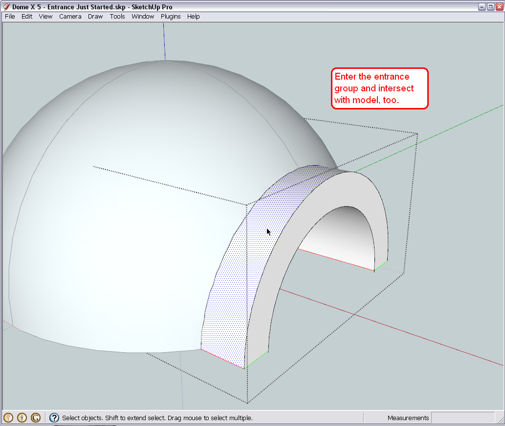
Now copy that bit (Ctrl+C) onto the clipboard. If you wish, at this moment you can even undo the intersect operation (we won't need those ugly lines on that entrance) as the undo will not undo whatever is on the clipboard.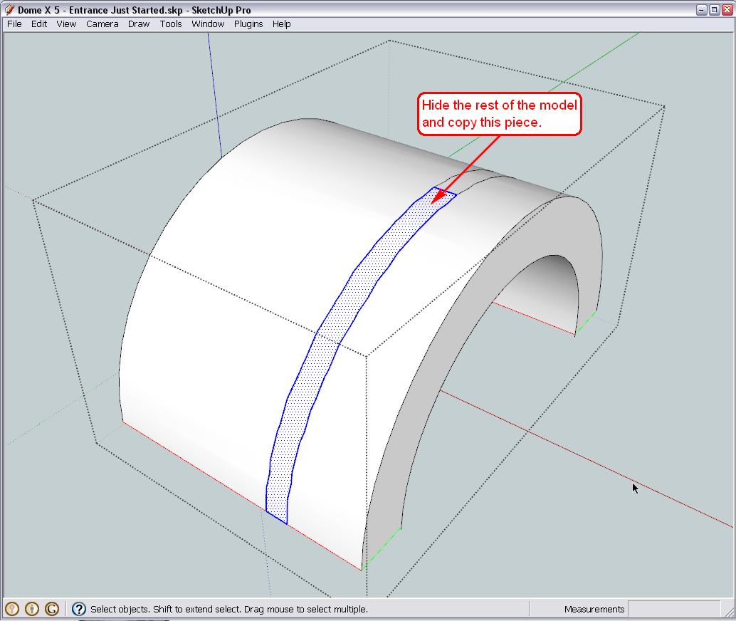
Finally enter the dome component (inside your group so do the double click twice) and go to Edit > Paste in place. The just copied face will be there for you. Reverse its face so the white is out and done.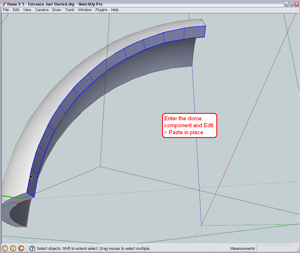
-
Hi Gaieus
Neat trick. Worked like a charm.Now I am at the 4th dome and this new trick you taught me doesn’t seem to be working as it did for the previous domes.
This is what I’ve done so far.
I hid the previous three domes and the last dome found below the 4th dome. I then intersected the 4th dome and something just didn’t look right but anyways I still proceeded with the cleanup. After the cleanup, I intersected my tunnel so I could create the face and then copy it to close the face of the 4th dome.
In the picture attached, you can see that this dome face didn’t close of as neatly as the others and left some portion of the face open as pointed out using the red arrows. Also, will I use the same solution to this problem on the last and final Dome which is labeled Sand Dome?
Lastly, with the previous dome, I had to draw in small lines to complete broken lines that were left after intersecting the tunnel to create the face. Just wanted to check if that’s ok as everything seems to look OK.
I’ve attached a model just after completing the 3rd dome / before starting the 4th dome. I have also attached my current model.
Thanks
Regards
D0me
Dome X 5 - Entrance Just Started.skp
-
Well, your entrance does not fully intersects the fourth dome. You will need to enter the entrance group and PushPull it until it fully intersects that dome, too.
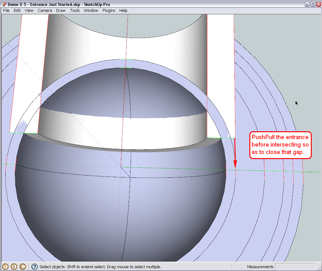
From this view, it is also apparent that you cannot use this entrance group to intersect the very middle dome (sand dome?) with. There has to be another solution. -
Hi Gai
I've pulled back the tunnel and then intersected. After that I cleaned up the opening but still something didn't seem right. I continued cleaning and drew back any broken lines. I then entered the tunnel and intersected to get the face for the 4th dome piece. I copied the face, undid the intersection. I entered the fourth dome and pasted the face in place.
Attached is what I ended up with. Definitely not looking right. I had to have gone wrong somewhere?With regards to the last dome (Sand Dome), what solution can you propose for me?
Thanks
Regards
D0me
-
Hi D0me,
Working on it... I see the problem and found the reason just need time to put everything together.
-
Okay, here is what I found. One little line segment was not created at the very edge of the intersection. The reason (probably) if that the intersect with model command does not intersect coplanar geometry (the intersect selected command does that) and there, as the width of the entrance and the innermost dome are exactly the same, that edge would have been coplanar. Here is a screenshot in X-ray mode (well I can imagine how confusing it is with all the lines everywhere).
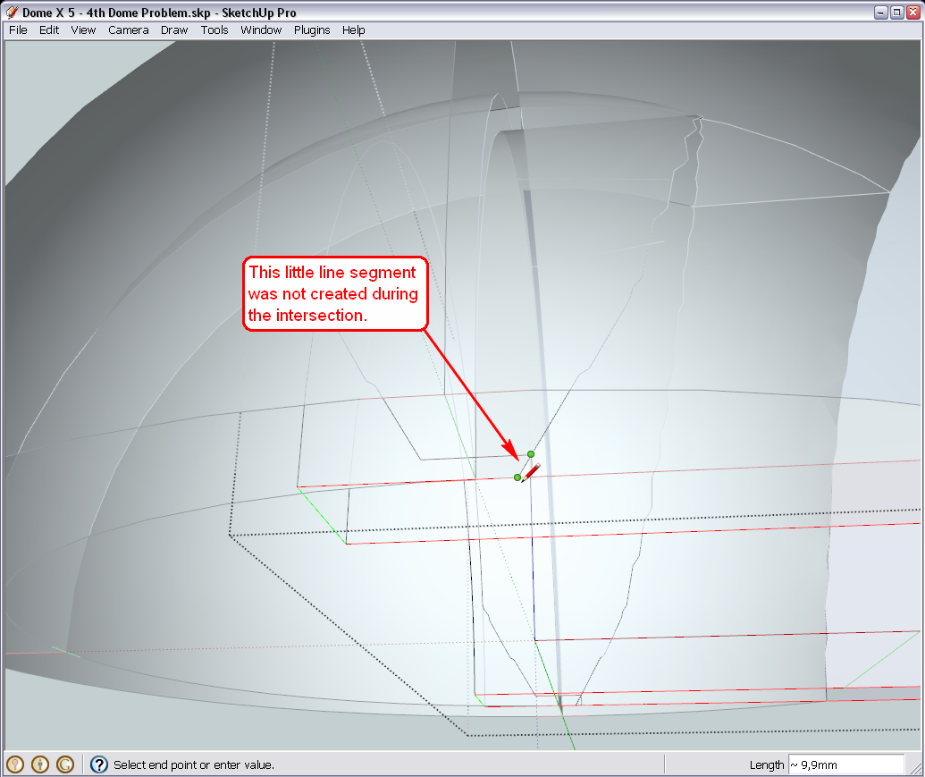
Also, to be able to work easier in this line jungle, I placed the different layers/shells of domes on different SU Layers. Open your layer dialog from te Window menu and turn them on/off to see the logic.
-
Hi Gaieus
Thanks for investigating and assisting in resolving my problem.After my previous post and just before reading your reply with the solution, I decided to take one more look at the model to try and see if I can figure out whats causing these problems with the last 2 domes.
@unknownuser said:
and there, as the width of the entrance and the innermost dome are exactly the same
I also picked this up when looking over the model. It then struck me that this could be the major cause in my last two dome, not intersecting properly. So I decided to take a few steps back. I had a backup of my model just after all my dome pieces were created and before creating the Arch Lines for the entrance. Instead of a 3" wall thickness for my tunnel, I chose a 1" thickness. I then went about following your tutorial and steps to make the tunnel. After creating the tunnel and intersecting all the Dome pieces, everything worked out perfectly. The problem was definitely my tunnel dimensions and specifically my wall thickness which made my tunnel exactly the same width as my second last dome.
All your teaching and the hard work and effort you put into tutoring me helped me diagnose the fault myself and I cant begin to explain how good it feels. Thanks Gaieus for bringing me so far along.
I've attached my model. Please can you have a look and see if everything is OK.
Now I am going to start the cylinder in the middle of my dome to create the bevel at the top.
Kind Regards
D0me
-
Nice, clean model.

I am really glad you got this far, too. One little thing maybe; there is a hidden edge in your entrance group that should be softened instead.
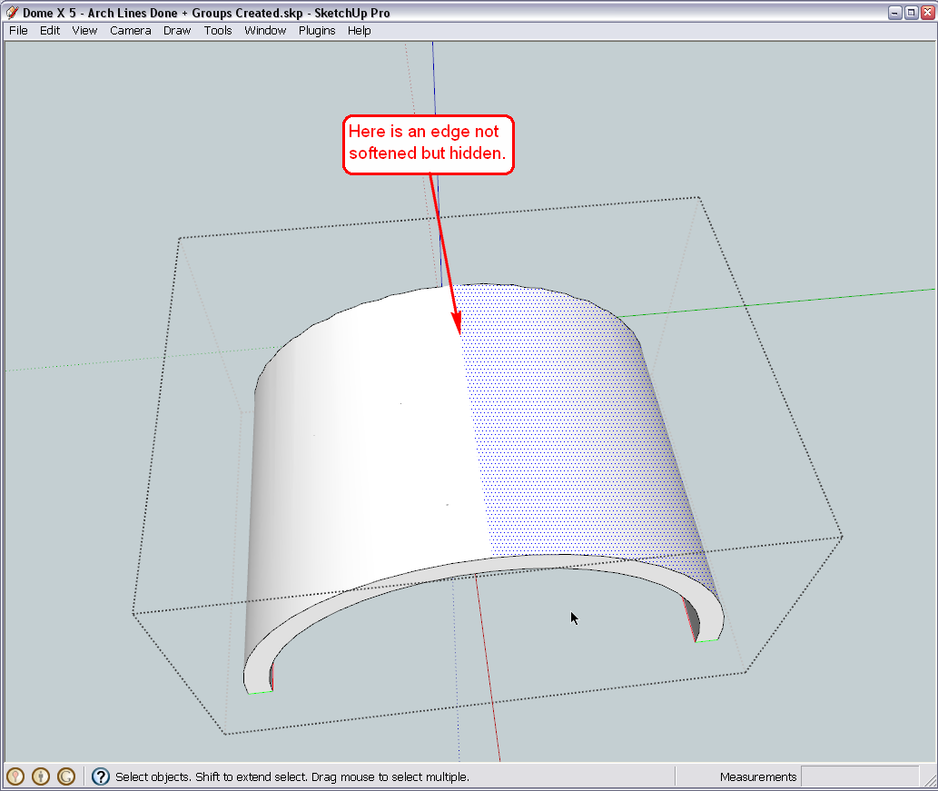
Turn on hidden geometry, select it, unhide (from the right click menu) and then soften it.This is all I can criticise in this model at a brief sight.
-
Thanks for pointing that out.
I actually used the erase to hide that dividing line.
I did the following as you advised.
- I select "View Hidden Geomatry"
- I then selected that dividing line and unhid it
- Lastly I right clicked the line and selected soften.
My Model is attached. Have I done the soften correctly?
Thanks
Regards
D0me
-
Hi Gaieus
I have started creating my 3" Diameter Cylinder in the middle of my domes and so far it’s going well. However I have few queries.
I have attached a picture of my model and specifically the Second Last and Last domes. I have pointed out the height of both these domes before and after the Cylindrical Pole intersected these dome. As can be seen, the last dome lost 0.4” in height now making it 11.6” instead of 12” and the second last dome also lost approx. 0.4” in height, now making it 12.6”, after the pole was intersected through both the domes.
I cant think of any way in which I can intersect the domes with the pole and still retain the original heights, except by redoing the entire model and accommodating for the Cylindrical Pole intersection.
Do you know of anyway this can be done and if not, I will probably redo the entire model but before I go ahead and do so, how do I ensure that my domes now will be high enough to accommodate the intersection of the pole and still retain the original height of which I require e.g Refractory dome should be 13” high.Secondly, its time for me to take this model a step further and start using what I have here to make what I require. Basically for a start, I need to Print My Model to Scale. I have a basic idea of what I require but I don’t know if it makes much sense the way I want it. I don’t know whether to start giving you my requirements just yet or should I wait till we get some clarity on the issue above in case this model needs to be redone.
Thanks
Regards
D0me
-
Well, each dome must have lost something! When you cut off the top of an arc (which there domes are in 2D actually), the "remainder" must be smaller. What is the function of this pole in there, by the way?
-
Hi Gaieus
The pole is used for 2 reasons.
- A Screeder (Wood Attached to a spinner) will be attached to the pole and used as my guideline when building the Domes.
- It will be used to create a Bevel at the top of the Dome and I guess this is the reason why my Dome lost a bit of height.
Yesterday, I began redoing the Model as an exercise to see how long it takes me and surprisingly I did up to this point in about an hour which is an accomplishment in itself for me.
Thanks
Regards
D0me -
Now when it is used only for construction (No.1) afterwards the "missing" material will not be replaced?
As for No.2 - what is the reason for that? Why do you need your dome "bevelled"? -
@d0me said:
Hi Gaieus
The pole is used for 2 reasons.
- A Screeder (Wood Attached to a spinner) will be attached to the pole and used as my guideline when building the Domes.
- It will be used to create a Bevel at the top of the Dome and I guess this is the reason why my Dome lost a bit of height.
The reason why you think your dome is lower is because you are comparing two different points on the arc:

You do not show the bevel on the bunghole yet. You can attach a knife to the spinner to cut the bevel to support the bung (as it will be cast separately.)
You can also use the pole to wire cut the segments if you want.
-
Hi Guys
Gaieus, the reason for the bevel in my dome is as per advice from Chrisglasier and after pondering over his advice a few posts back, i realized that this will strengthen my dome even more.
Regarding point 1, you are right. After construction, the missing material will no longer be there. Should I modify my model in such a way that it accommodates for any material that will be missing (e.g Pole, Screeder, etc).Chris, I'm a little confused with regards to your last post. You mentioned that I was comparing 2 different points on the arch. Is it possible to show me where I should mark the correct points to compare on My Model attached on previous posts both before and after adding the bunghole?
Any tips on how I should add the bevel to the Bunghole?
Lastly, how should I attach a knife to the spinner? May I ask if it's OK for you to maybe illustrate it on a picture or better yet on my model so I get a better understanding?Thanks
Regards
D0me
Advertisement


