Help Me Draw A Dome [TUTORIAL]
-
Well, your entrance does not fully intersects the fourth dome. You will need to enter the entrance group and PushPull it until it fully intersects that dome, too.
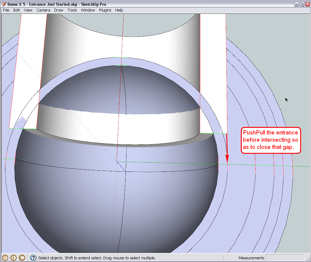
From this view, it is also apparent that you cannot use this entrance group to intersect the very middle dome (sand dome?) with. There has to be another solution. -
Hi Gai
I've pulled back the tunnel and then intersected. After that I cleaned up the opening but still something didn't seem right. I continued cleaning and drew back any broken lines. I then entered the tunnel and intersected to get the face for the 4th dome piece. I copied the face, undid the intersection. I entered the fourth dome and pasted the face in place.
Attached is what I ended up with. Definitely not looking right. I had to have gone wrong somewhere?With regards to the last dome (Sand Dome), what solution can you propose for me?
Thanks
Regards
D0me
-
Hi D0me,
Working on it... I see the problem and found the reason just need time to put everything together.
-
Okay, here is what I found. One little line segment was not created at the very edge of the intersection. The reason (probably) if that the intersect with model command does not intersect coplanar geometry (the intersect selected command does that) and there, as the width of the entrance and the innermost dome are exactly the same, that edge would have been coplanar. Here is a screenshot in X-ray mode (well I can imagine how confusing it is with all the lines everywhere).
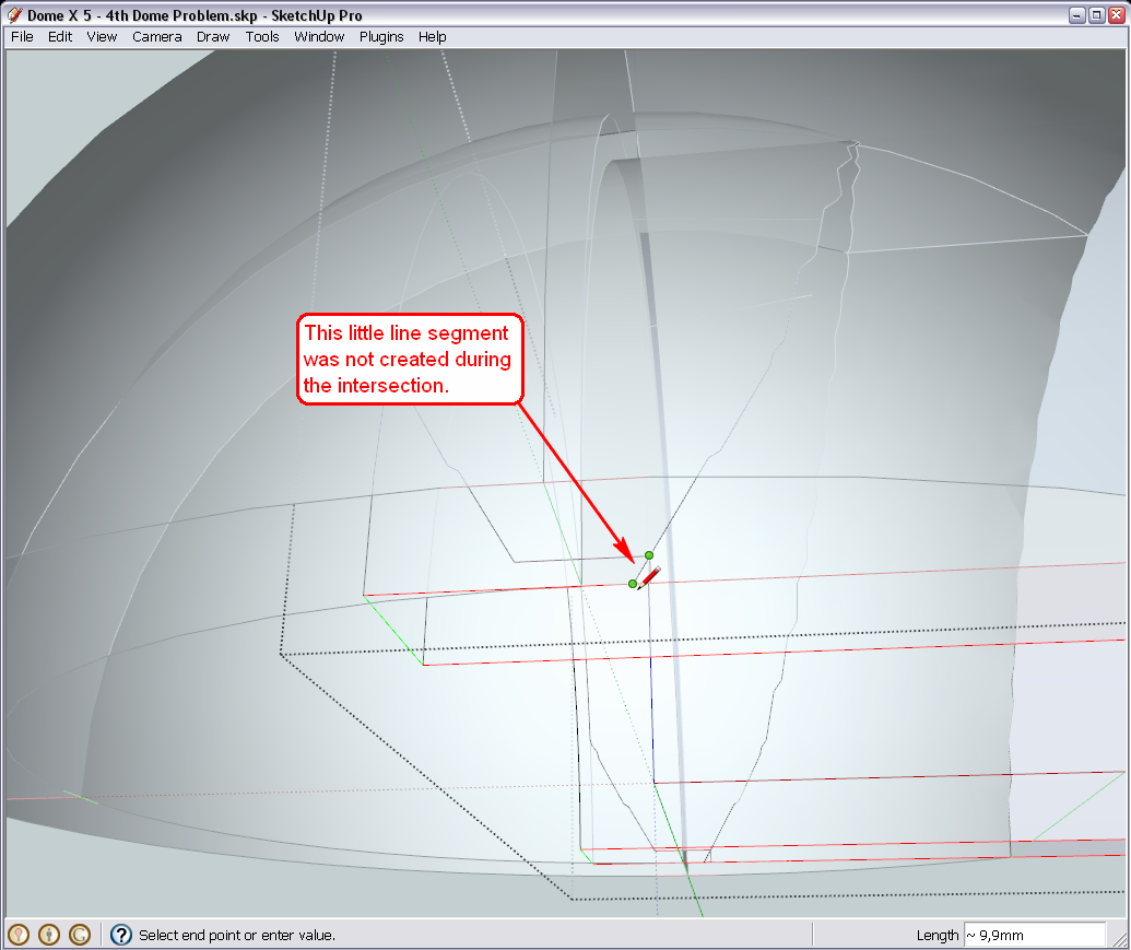
Also, to be able to work easier in this line jungle, I placed the different layers/shells of domes on different SU Layers. Open your layer dialog from te Window menu and turn them on/off to see the logic.
-
Hi Gaieus
Thanks for investigating and assisting in resolving my problem.After my previous post and just before reading your reply with the solution, I decided to take one more look at the model to try and see if I can figure out whats causing these problems with the last 2 domes.
@unknownuser said:
and there, as the width of the entrance and the innermost dome are exactly the same
I also picked this up when looking over the model. It then struck me that this could be the major cause in my last two dome, not intersecting properly. So I decided to take a few steps back. I had a backup of my model just after all my dome pieces were created and before creating the Arch Lines for the entrance. Instead of a 3" wall thickness for my tunnel, I chose a 1" thickness. I then went about following your tutorial and steps to make the tunnel. After creating the tunnel and intersecting all the Dome pieces, everything worked out perfectly. The problem was definitely my tunnel dimensions and specifically my wall thickness which made my tunnel exactly the same width as my second last dome.
All your teaching and the hard work and effort you put into tutoring me helped me diagnose the fault myself and I cant begin to explain how good it feels. Thanks Gaieus for bringing me so far along.
I've attached my model. Please can you have a look and see if everything is OK.
Now I am going to start the cylinder in the middle of my dome to create the bevel at the top.
Kind Regards
D0me
-
Nice, clean model.

I am really glad you got this far, too. One little thing maybe; there is a hidden edge in your entrance group that should be softened instead.
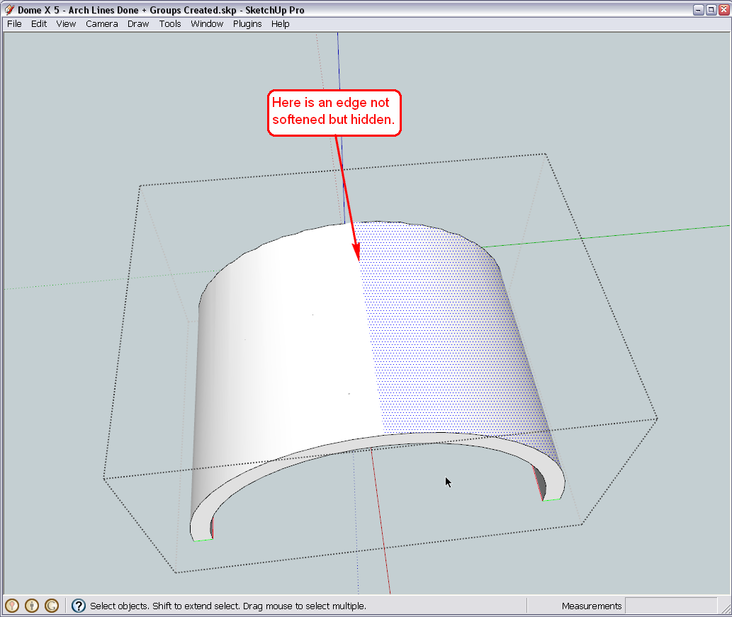
Turn on hidden geometry, select it, unhide (from the right click menu) and then soften it.This is all I can criticise in this model at a brief sight.
-
Thanks for pointing that out.
I actually used the erase to hide that dividing line.
I did the following as you advised.
- I select "View Hidden Geomatry"
- I then selected that dividing line and unhid it
- Lastly I right clicked the line and selected soften.
My Model is attached. Have I done the soften correctly?
Thanks
Regards
D0me
-
Hi Gaieus
I have started creating my 3" Diameter Cylinder in the middle of my domes and so far it’s going well. However I have few queries.
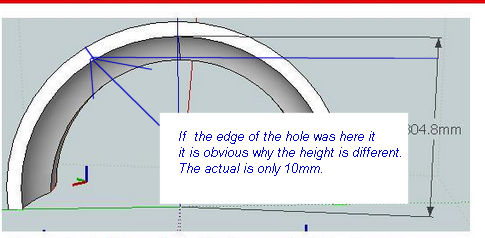
I have attached a picture of my model and specifically the Second Last and Last domes. I have pointed out the height of both these domes before and after the Cylindrical Pole intersected these dome. As can be seen, the last dome lost 0.4” in height now making it 11.6” instead of 12” and the second last dome also lost approx. 0.4” in height, now making it 12.6”, after the pole was intersected through both the domes.
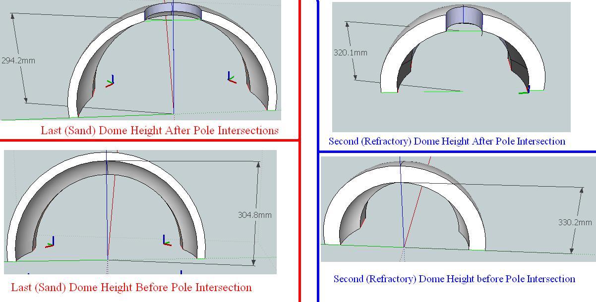
I cant think of any way in which I can intersect the domes with the pole and still retain the original heights, except by redoing the entire model and accommodating for the Cylindrical Pole intersection.
Do you know of anyway this can be done and if not, I will probably redo the entire model but before I go ahead and do so, how do I ensure that my domes now will be high enough to accommodate the intersection of the pole and still retain the original height of which I require e.g Refractory dome should be 13” high.Secondly, its time for me to take this model a step further and start using what I have here to make what I require. Basically for a start, I need to Print My Model to Scale. I have a basic idea of what I require but I don’t know if it makes much sense the way I want it. I don’t know whether to start giving you my requirements just yet or should I wait till we get some clarity on the issue above in case this model needs to be redone.
Thanks
Regards
D0me
-
Well, each dome must have lost something! When you cut off the top of an arc (which there domes are in 2D actually), the "remainder" must be smaller. What is the function of this pole in there, by the way?
-
Hi Gaieus
The pole is used for 2 reasons.
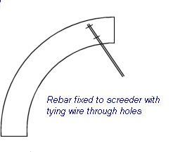
- A Screeder (Wood Attached to a spinner) will be attached to the pole and used as my guideline when building the Domes.
- It will be used to create a Bevel at the top of the Dome and I guess this is the reason why my Dome lost a bit of height.
Yesterday, I began redoing the Model as an exercise to see how long it takes me and surprisingly I did up to this point in about an hour which is an accomplishment in itself for me.
Thanks
Regards
D0me -
Now when it is used only for construction (No.1) afterwards the "missing" material will not be replaced?
As for No.2 - what is the reason for that? Why do you need your dome "bevelled"? -
@d0me said:
Hi Gaieus
The pole is used for 2 reasons.
- A Screeder (Wood Attached to a spinner) will be attached to the pole and used as my guideline when building the Domes.
- It will be used to create a Bevel at the top of the Dome and I guess this is the reason why my Dome lost a bit of height.
The reason why you think your dome is lower is because you are comparing two different points on the arc:

You do not show the bevel on the bunghole yet. You can attach a knife to the spinner to cut the bevel to support the bung (as it will be cast separately.)
You can also use the pole to wire cut the segments if you want.
-
Hi Guys
Gaieus, the reason for the bevel in my dome is as per advice from Chrisglasier and after pondering over his advice a few posts back, i realized that this will strengthen my dome even more.
Regarding point 1, you are right. After construction, the missing material will no longer be there. Should I modify my model in such a way that it accommodates for any material that will be missing (e.g Pole, Screeder, etc).Chris, I'm a little confused with regards to your last post. You mentioned that I was comparing 2 different points on the arch. Is it possible to show me where I should mark the correct points to compare on My Model attached on previous posts both before and after adding the bunghole?
Any tips on how I should add the bevel to the Bunghole?
Lastly, how should I attach a knife to the spinner? May I ask if it's OK for you to maybe illustrate it on a picture or better yet on my model so I get a better understanding?Thanks
Regards
D0me -
Well, a very quick and dirty "fix" would be to scale your model up accordingly. Certainly a uniform scale would be best but of course in that case, everything will be a bit bigger.
Now I have to rush to the bank and then to the accountant (darn financial issues) and don't know when I am back but we can eventually find out something.
-
-
Hi Guys
Chris, thanks for the explanation using images. Understand it much better now. I’ll definitely keep those tips in mind.
Gaieus
Good luck with sorting your financial issues. They are the worst thing to resolve.
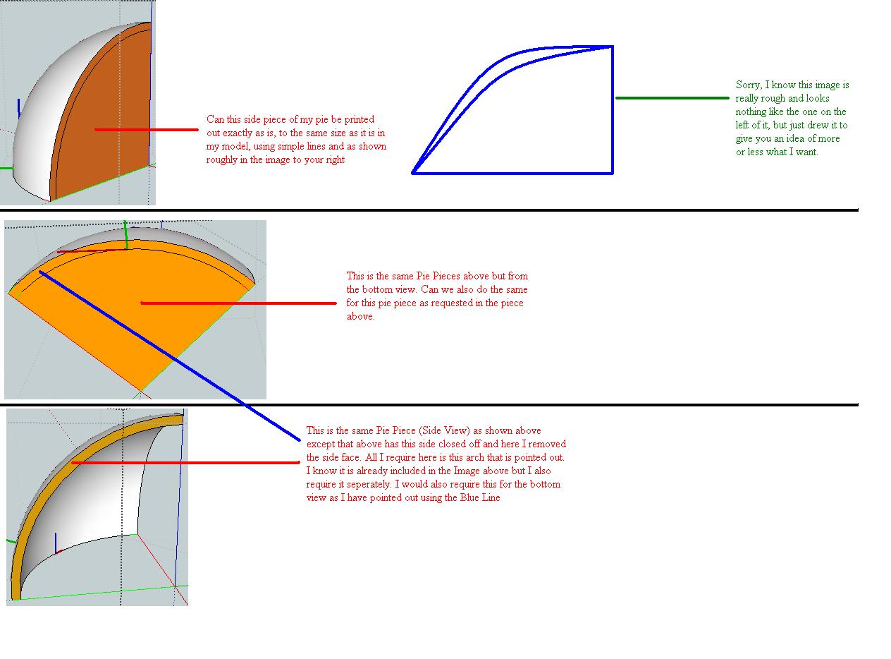
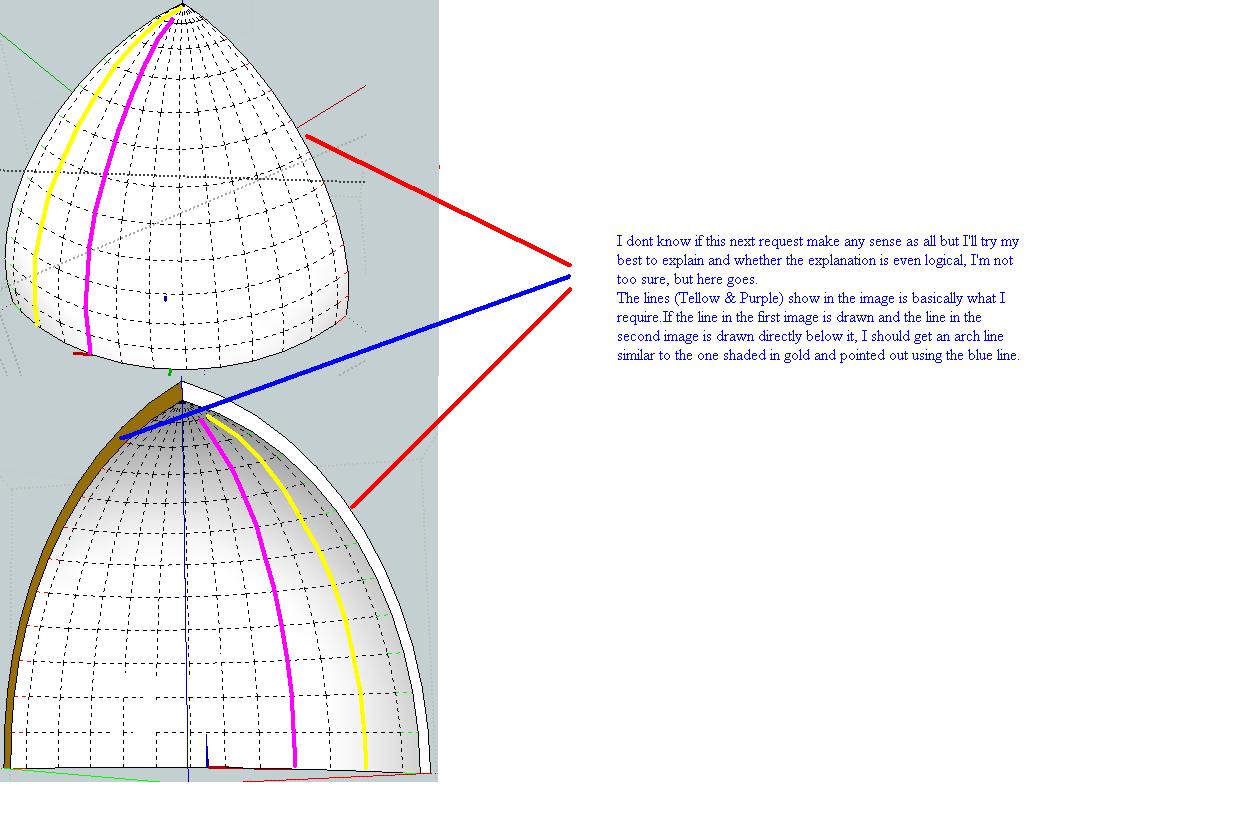
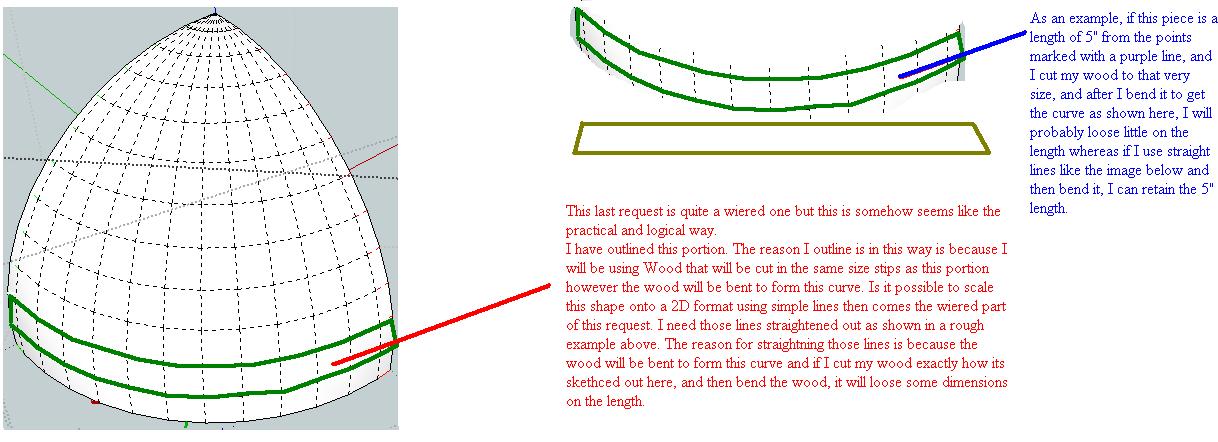
Whenever you can assist will be perfectly fine with me. No Rush.I thought, while we are trying to resolve this situation, we can start thinking about how to get this model printed to scale and more so, how we going to draw this model in simple 2D lines so I can easily make my guides. If there is need to redo my model, this shouldn’t be an issue as I am very familiar with how to do it in a short space of time thanks to you.
My explanations as usual don’t seem to make much sense but hope the images do. If you need me to clarify anything, let me know.
Thanks
-
The transition from model to construction data should not be like this. I would like some time to explain. This is an important part of my work. Can you give some time - like tomorrow or the next day?
-
@chrisglasier said:
The transition from model to construction data should not be like this. I would like some time to explain. This is an important part of my work. Can you give some time - like tomorrow or the next day?
Sure Chris. I'd love to hear your advice on how the transition should be done.
Your advice is always welcomed and I look forward to hearing it.Don't keep me in suspense for too long. I'm really anxious to compare your advice with the way I thought it should be done.
Take care
Regards
D0me -
Make the model to visualise how the real thing will work, how it will look and how it can be made. Then as far as possible use the dimensions you used to draw it in Sketchup to draw it on the plywood, bricks or whatever exists. I remember that, in your crusade to make things difficult (CMTD), that the arc of the dome is not regular, so you will have to make a template.
I am not against printing one. In fact I did that once for a bar canopy that was like part of an airplane wing. It took up to eight sheets of A0 paper for each truss. In those days I had all sorts of equipment including a plotter (and a joinery shop). But really I think the best thing for you is to lay a grid over a parallel projection of a standard view of the model, and then transpose the intersections onto a full scale grid on plywood to make the spinner. You won't need any other templates.
But you will need some 2" wire nails, twine, measuring tape, marker pen, shovel, broom, hawk and finishing trowel. You may find a wood float useful as well. Aim to make the d0me accurate to +- 10mm.
I have never used rapid hardening concrete but I understand it is only workable for 20 minutes or so. You really need to understand how to use the spinner and these tools before mixing the concrete. I don't understand why you want multiple d0mes (CMTD?) but I suggest 2" is a minimum thickness for any one casting. You should consider using a bonding agent.
If you want to wire cut the segments make a plywood collar to slip over the pole and attach straining wires at its quadrant points. Lay out your brick base square so that there is a joint at each of the base quadrant points. (Not CMTD herringbone - which will never be appreciated anyway). After cutting and scooping out the bunghole, push the collar down the pole and align the wires in the brick joints. Cut the d0me like cheese.
I can only give you my opinion; please remember I have only experience making an adobe d0me.
When's the kickoff?
-
As for printing to scale in general, the method should be this:
- Make sure you are in Parallel projection mode (Camera menu).
- Also make sure you are in any of the Standard views (Camera menu again).
- Then set your print dialog (File menu > Print) like this below (I have set it to 1:5 now as that can still fit on an A4 page I "virtually" printed the model into a pdf file - see also attached).
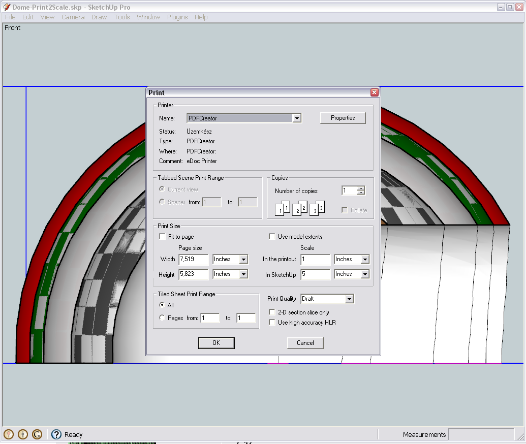
Now I also added a section plane to the model so that you can print the section cut to scale. If you had the Pro version, you could even export this cut into a vector format to use it in some external CAD software or such. Certainly the cut looks quite ugly this way but with some plugins we can easily fix that later - the theory will be the same.
Hello! It looks like you're interested in this conversation, but you don't have an account yet.
Getting fed up of having to scroll through the same posts each visit? When you register for an account, you'll always come back to exactly where you were before, and choose to be notified of new replies (either via email, or push notification). You'll also be able to save bookmarks and upvote posts to show your appreciation to other community members.
With your input, this post could be even better 💗
Register Login


Advertisement