Help Me Draw A Dome [TUTORIAL]
-
Yes, that is exactly what I want. The 4 inches will be added to the 3 inches. Its all 1 dome at the end of the day.
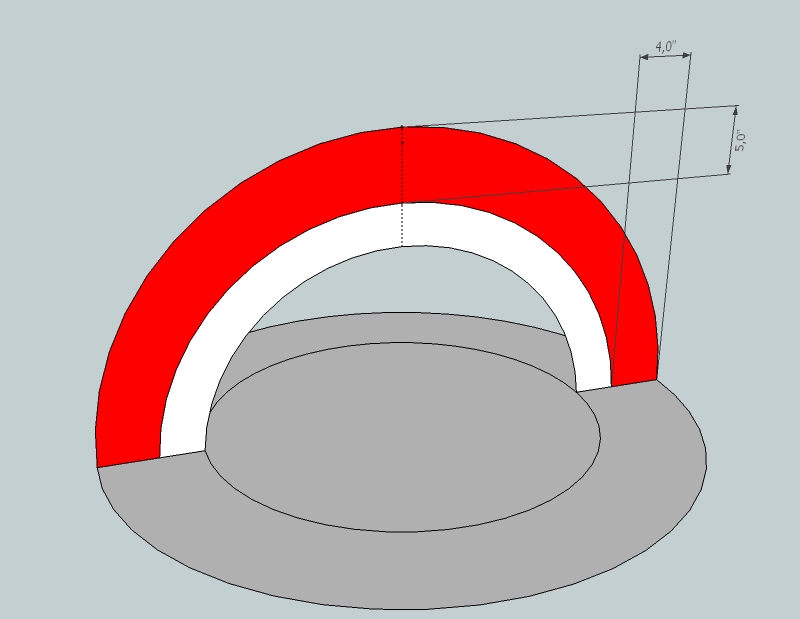
The file learning2 is correct except that the additional 4 inches should be in red for example so I can mark measurements for each thickness seperately. -
But that's not exactly 4" additionally 'cause we have added an extra inch on top.
-
Hi
Is the extra inch on top unavoidable?
I was wondering also whether the sides of the extra 4" is 4" exactly and only the top has moved to 5 Inches. Maybe to uncomplicate things, we can leave that out. I can manually make a note on the drawing of the 4". It's not imperative that it be there. I just thought I'd put as much detail as possible so theres less room for mistake.
Thanks
-
It can be there - it wouldn't cause any extra work or issue. Just mentioned (and of course, the two arcs of the red stripe are not parallel now but c'est la vie).
Well, in nay case, if you modify the drawing now by adding the extra ring of circle as well as the extra arc (and connect the ends) just like the steps for the previous one, simply do not delete the mid-circle and the inner arc but leave it there so we will make a dome with a double shell.
-
That's Cool
So where do go from here?
-
shhh,,
a very cool "private lesson" dear Gai.. well done. Just watch in silence and follow..
(Hi Dome, you could have fallen on a worst professor do you know , may be it would be better to go to the end of the first demand before add some complex further steps...)
simon. -
Have you finished it with the double arches and circles?
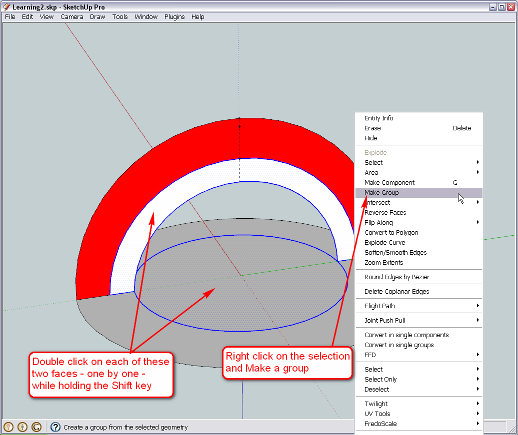
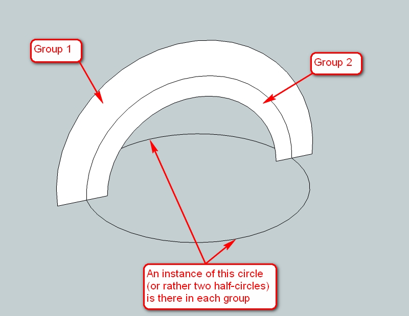
Now as we have quite complex and touching geometry (I don't mean it emotionally but that the two, separate shells of the dome will inevitably touch and affect each other's geometry whatever we do with them), we need to separate the two domes. This goes by grouping.
We will group two sets of a circle and a stripe of arc face together. By double clicking on a face, you select the face AND its bounding edges. When there are more entities to select in a "bunch", keep the Shift key pressed while clicking.
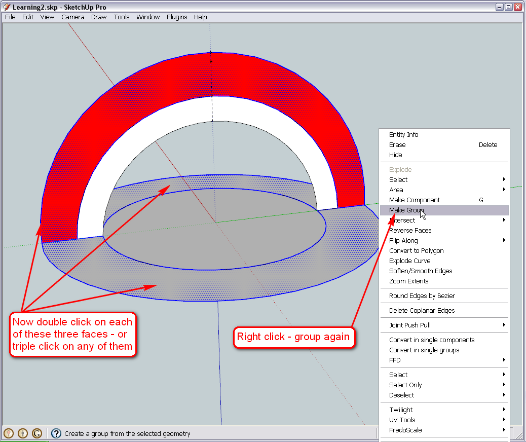
Now the other set - again, Shift key + double click - but we have one more face to select as our ring is divided into two.Another method could be to triple click anywhere - this will select everything that is connected in the same editing context (i.e. not what's in the group any longer - after all that's what grouping is; separating geometry). This is why we could not use triple clicking above - it would have selected everything.
@simon le bon said:
a very cool "private lesson" dear Gai.. well done.
Just watch in silence and follow..Asx well as I keep following your extensive and excellent tutorials, Simon!
Cheers;

-
Hi Simon.
I wouldn't ask for a better teacher than Gai. He has certainly impressed me and I'm sure alot of others on this forum.
And again Thanks Gai
-
There is a handful of secondary school students (14-15-y-o) I give some extra tutoring of SU weekly. A lot of fun I have to say.
So where are you at with the grouping?
-
Ok Done.
I hope I've done it correctly. Please check.I am going to be on the road for a few hours, so I will continue a little later.
Let me know what to do next.Thanks
-
Well, some arc segments again

But in fact, the ideal solution is somewhere between yours and mine. I uploaded a new version that is cleaned up and "optimised" for further work.
-
Hi Gai
Sorry for the delayed reply.I've Downloaded the optomised version.
Ready to continue, Sir. -
Hi D0me back.
Okay, it seems that it was not very well optimised (see below) but without a plugin, we cannot do it better anyway.
So let's see - let's deal with the inner dome first. We need to "get inside" the group to be able to work with the geometry. This is called "editing" and you can do it tree ways:
- select the group > go to Edit menu > Group (at the bottom) > Edit.
This is tiresome however. - select the group > right click > edit.
well, somewhat better. - double click - and you are already in - so let's use this
We are going to use the Follow me tool to "lathe" the dome face around the circle. First step is to establish the path we are going to spin (lathe) the face around so select both halves of the circle:
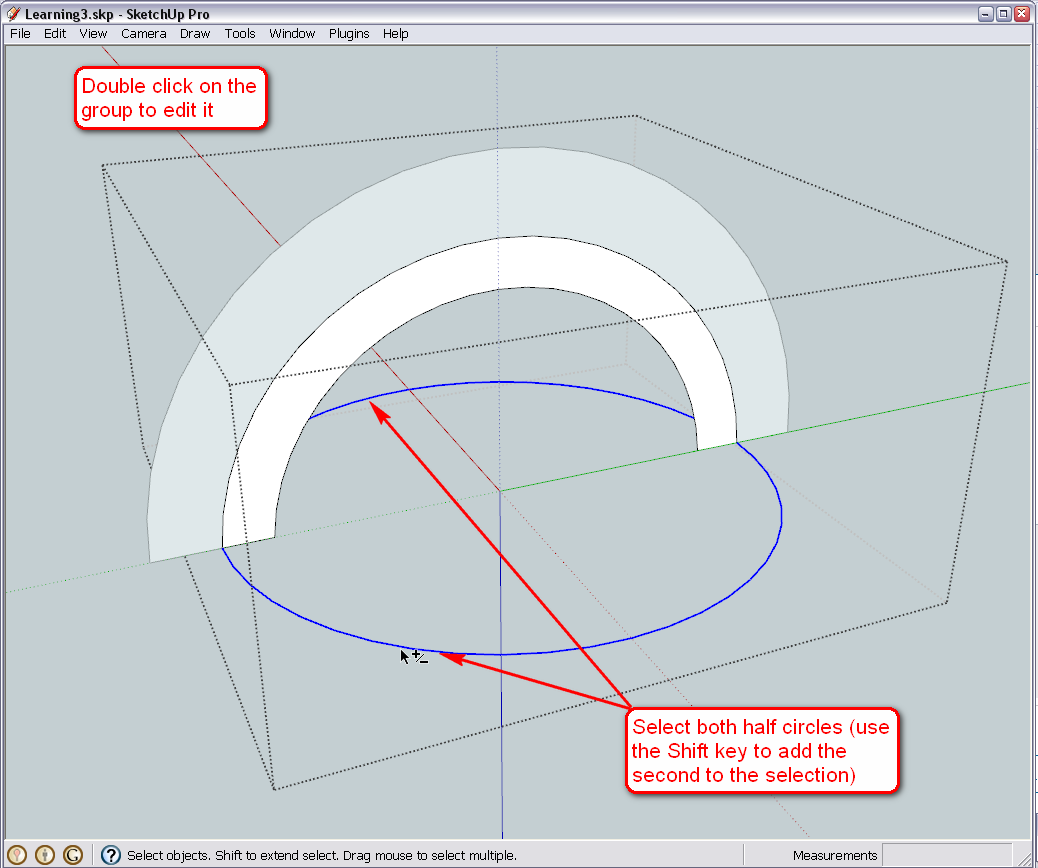
Now select the follow me tool from either the Tool menu or better to activate the Modification toolbar from the View > Toolbars menu and click on the dome face. Don't worry if you see your circle deselected when you pick the Follow me tool - SU will "remember" the path.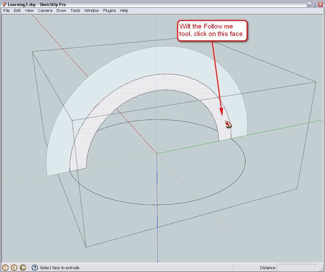
Now this is something you end up with. More often than not, the faces are oriented correctly and the dome is generally smooth - now this is not probably because due to the two arcs meeting, the arc entity was exploded at a point (we could have welded it with a plugin but leave plugins for later).
So first, we reverse all back faces so that we can see only the front faces: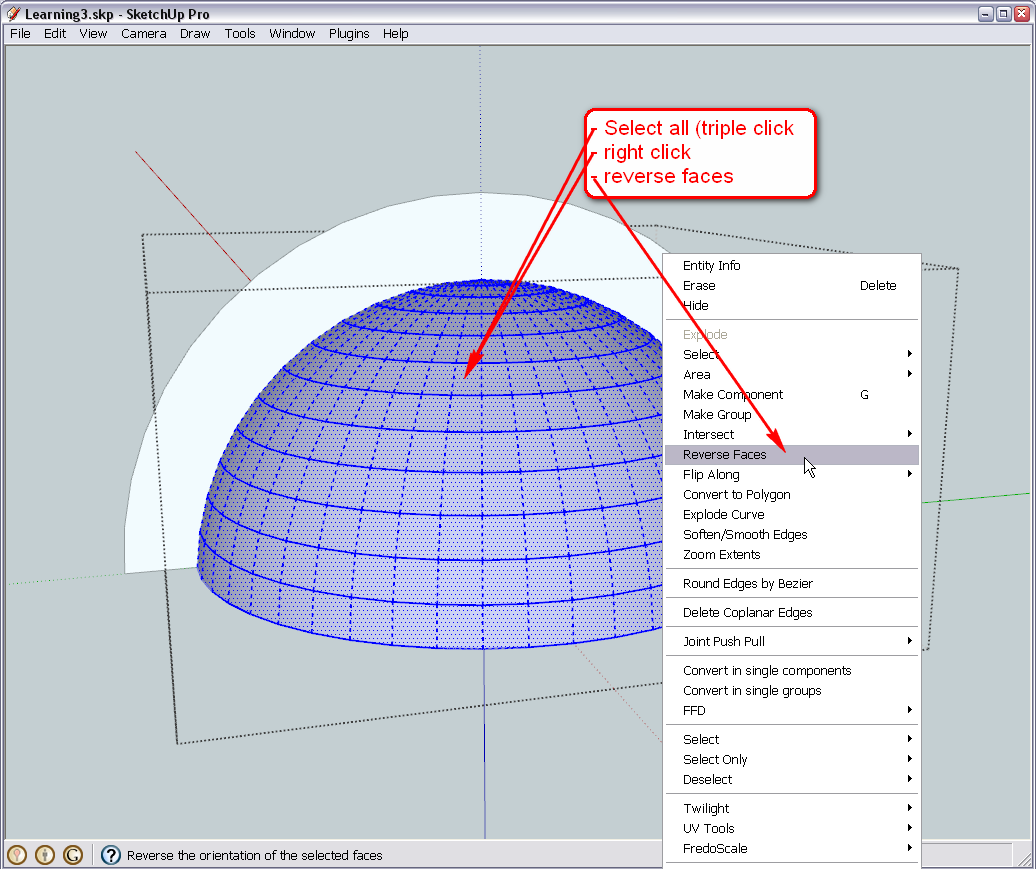
Now let's smooth the dome while it is still selected (if you lose the selection, triple click again).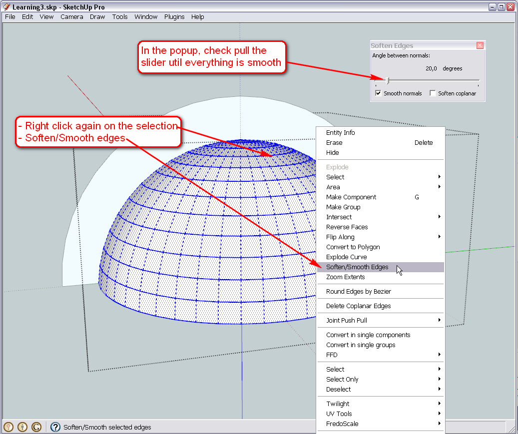
Let me know when you are done - but you can repeat the steps with the outer dome on your own - they are exactly the same (maybe no need for reversing or softening but even better). - select the group > go to Edit menu > Group (at the bottom) > Edit.
-
I am ready with these steps so far...
-
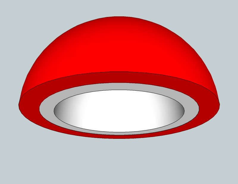
Yes, Yes, Yes.
I got it. Feels so good to achieve this
Never thought this would be so excitingAs you can see I've already shaded the top dome in red. The rim of the inner dome is Green and the inside of the inner dome is yellow.
So, where to from here?
-
Okay, now we are going to make some preparations to slice up your melon.
Previously we have seen that curved surfaces are made up of practically flat (just visually smoothed) facets. This is what we are going to utilize now. You need to divide the domes by 6 which is a lucky number as our circles we built it on top have 48 segments that is dividable by 6 (the default 24 is also - so whenever you need an odd number to divide your circles with, plan ahead...)
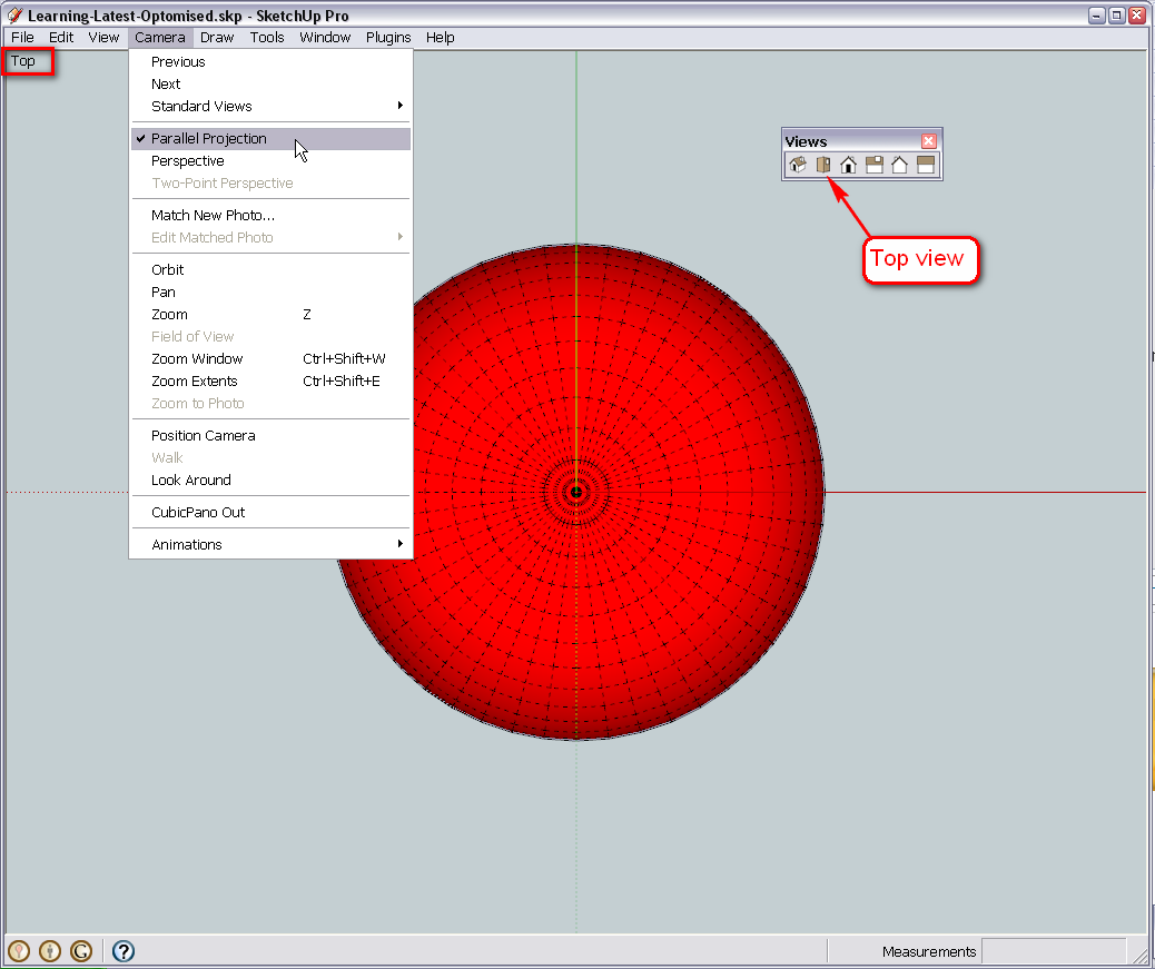
First, turn on hidden geometry under View > Hidden geometry. This will reveal the facets and the dividing (though segmented) arcs. Then (if you haven't done so yet), activate the Standard views toolbar from View > Toolbars (though they are also accessible from the Camera menu > standard views). Go to "Top" mode and also into Parallel projection so that you can see everything nicely aligned to the axes and orthogonal. I myself only use parallel projection in these cases but others often prefer to model this way.
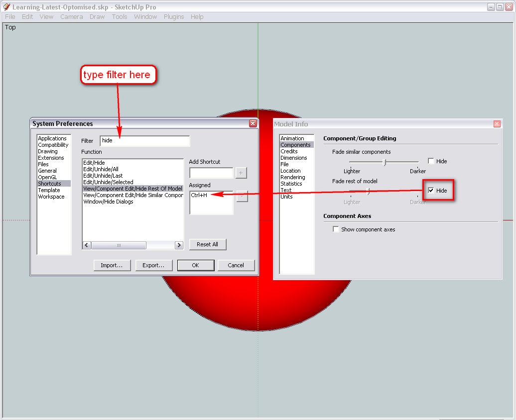
Though now we have a nice view, I already know that while working on the little pieces of the geometry here, one or the other shell of the dome will be very much in our way to access parts of the other. Fortunately we have a very nifty tool to overcome this. On the right, you can see the model info dialog (Window menu) > Components tab. Although groups are not components, they behave the same way in many respects and this function works with groups, too; Check the "Hide rest of model" (when editing a group/component - in this case, ONE of our shells).Since this item is hidden quite much (even under View > component edit > ... menu), and we may need it quite often in the biggest urge, best is to assign a shortcut key to it. It can be found under Window > Preferences. I use Ctrl+H but it can be anything.
One more thing - either activate the Face styles toolbar (now you already know where these are) of under View > Face styles, turn it to monochrome. This is better to model little parts like this as well as you will always see where there are back faces.Now start editing one of your groups and find out how you could easily delete parts from the hidden geometry. If you find it boring, don't go on because this is NOT the way we are going to do it - by the way, it is high time to make a backup file because when we finish (with another method - intersecting with a plane), you will notice that it is not the way you wanted it and we will need to start over.
If you want to avoid this, find out NOW what we need to do. Some hints in this topic:
http://forums.sketchucation.com/viewtopic.php?f=79&t=24578Another hint - we are going to use the rotate tool extensively.
Now I have an urgent meeting with a friend in my regular, local, corner bar, so I quit but if I can, I will get back. If it is too late for you (I think you are a bit ahead of time than me), I can still prepare the home-work for tomorrow.
In the meanwhile, also think about what other changes you would like to make in later phases.Cheers;

-
Oh yes, and forgot to say that your dome is completely upside down. Select everything (both groups) in your mode > right click on the selection and "Flip along..." the blue axis.
-
Hi Gaieus
I have allocated my shortcut key and backed up my file at this stage.
I didn't realize my dome was upside down but thats sorted now.With regards to additional changes in the dome, I think we have everything covered at the moment.
Here's a recap- Split dome into 6 equal parts.
- Allow removal of each part individually and combining them together again.
- Underneath the dome is a covering so to say. I would like to be able to remove this covering and also re-attach it if need be.
I also need the dome to sit on a platform. The platform has it's own dimensions.
Do you need these now or can we incorporate that later after the dome is complete?I think that's about it for now, untill something else pops up in my head but I highly doubt it. I have thought this over real hard and can't really think of anything else.
Regards
D0me -
It's a dome's class in depth

-
Rivetting ... really
Hello! It looks like you're interested in this conversation, but you don't have an account yet.
Getting fed up of having to scroll through the same posts each visit? When you register for an account, you'll always come back to exactly where you were before, and choose to be notified of new replies (either via email, or push notification). You'll also be able to save bookmarks and upvote posts to show your appreciation to other community members.
With your input, this post could be even better 💗
Register Login


Advertisement