[Plugin] Milling Tools
-
@mitcorb said:
Just out of curiosity, is this in any way related to Fredo6's Bezier tools added polyline tools for dogbone and t-bone polylines? And was work discontinued for that reason?
The tools where done in parallel - initiated by a request here at the forum.
I simply haven't had time to work on this. Since I don't do CNC work myself it'd ended up as low priority. -
I don't do CNC work either. I was just thinking maybe Fredo's feature could fill a temporary need? They are obviously different approaches.
-
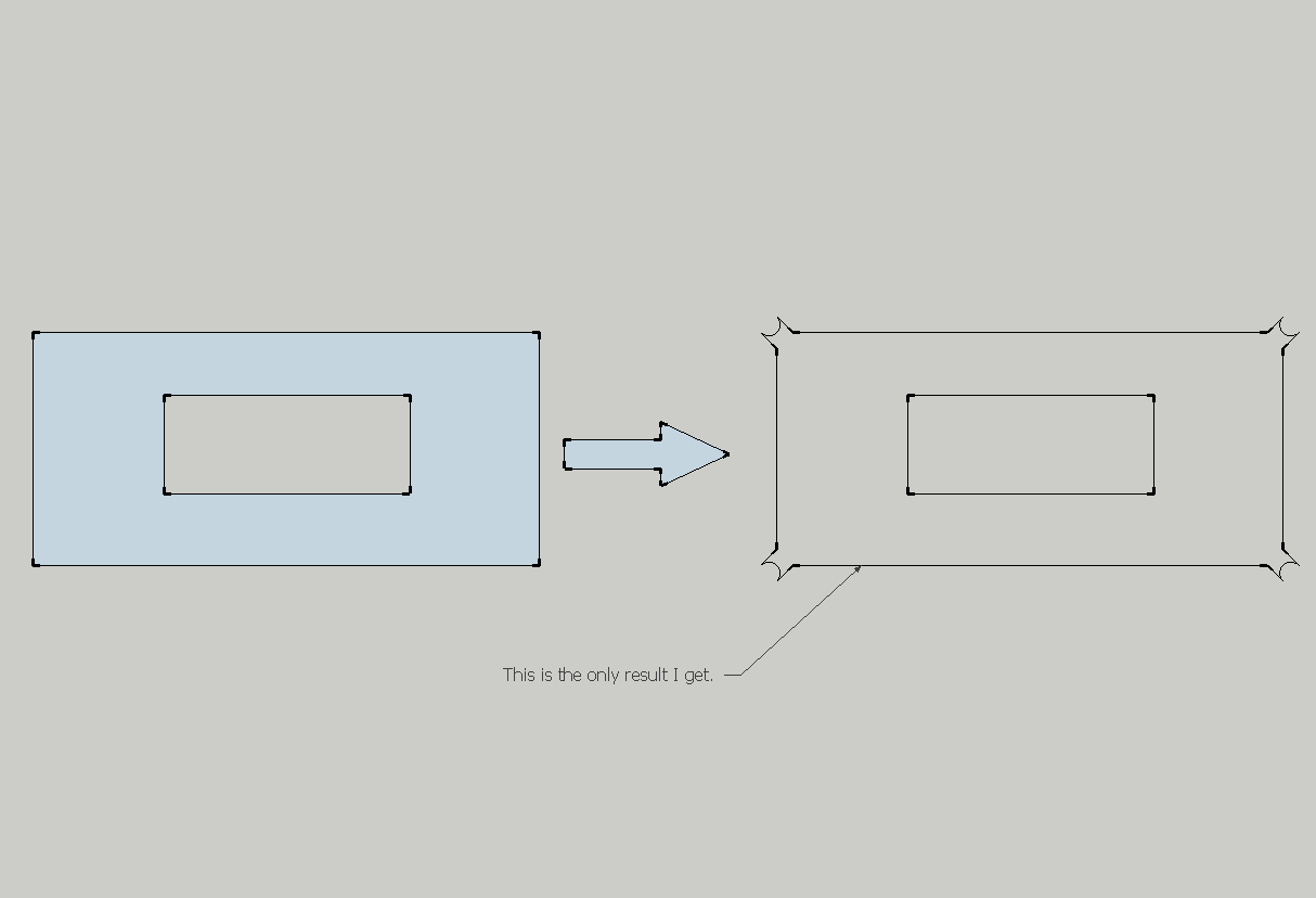
I encounter problems with this model. I also tried on a simple rectangle and I get strange results. Maybe I don't know how to use it?
It would be useful to get the actual contour line and this plugin to create a path (inner/centered/outer) on how the milling head will perform. In the first post, I've seen some images that illustrate exactly this, but my results were bad.

- I don't know why "Milling result.png" is not shown


- I don't know why "Milling result.png" is not shown
-
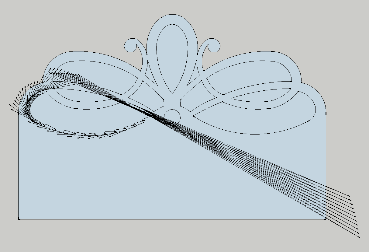
In your attached model, there are errors listed in the Ruby Console. The plugin has not been tested on such complex and curved shapes.
@unknownuser said:
It would be useful to get the actual contour line and this plugin to create a path (inner/centered/outer) on how the milling head will perform. In the first post, I've seen some images that illustrate exactly this, but my results were bad.
You would like the path you see in the preview as actual geometry?
-
This model if yours has revealed several issues with this plugin...

-
@thomthom said:
You would like the path you see in the preview as actual geometry?
I would like to draw the actual geometry in Sketchup, but the plugin to alter my edges (offset/inset or leave them unaltered, just fillet corners). Because the milling bit can perform on the left, on the right or on the center of the line.
This plugin could be a very powerful one in the future... (offtopic: Now I have some problems with DXF export from SketchUp and importing in CNC software. Some line elements (especially arcs) are mirrored outside of board perimeter). Maybe AutoCAD and SketchUp export DXF in different manners.)
-
@thomthom said:
This model if yours has revealed several issues with this plugin...

It's my model...actually is something I do now. The curves have a lot of segments because it will be sent to CNC and I have some problems with arcs in DXF export. Polylines are ok, but if there are less segments, it will reflect in manufactured piece.
-
I'm thinking that there might be a need of a tolerance limit. If the angle between two edges are within a range close to co-linear it should skip the corner...
-
@thomthom said:
I'm thinking that there might be a need of a tolerance limit. If the angle between two edges are within a range close to co-linear it should skip the corner...
Maybe this as a option... because if I set that o CNC, it will make a tangent radius between that two edges in the pieces (radius equal with tool radius). So, if I want that result, to be able to obtain it.
-
Trying to track down the various issues.
One that I see is that the orientation of the face normal matters. When I flipped the face it was behaving more as expected. but there where still various issues.
-
@thomthom said:
When I flipped the face it was behaving more as expected.
Indeed, I would never think on that. Beside Dog-Bone fillet, you could add option for regular rounding. dog-bone is used mainly on metal sheets, to avoid fracturing on cut out corner. But, if I need to carve a piece from a sheet of material (see my headboard), that dog-bone effect is not good. Instead, what is needed is a offset with filleted corners.
-
The thing is - the normal of the face shouldn't matter. ...but currently it does... it't just another one of the issues.
-
Doesnt work on sketchup 8....
-
@boilingsnow said:
Doesnt work on sketchup 8....
Yes it does.
Can you describe "what doesn't work"? Error messages? (if you have the Ruby Console open) Unexpected results? (Post sample model) Any screenshots that explains further?
I can't provide any further assistance without any info to work with. -
Nice. Half the way.
Still missing T-Bones.

Also, a lot of time I need to hide the holes produced by Dog-Bones. Like this one:

-
@dacicusan said:
T-Bones.
Dog-Bones.
http://sketchucation.com/forums/viewtopic.php?f=323%26amp;t=13563
Robert
-
Hi ThomThom,
I love this plugin. it helps me to assess nesting very efficiently for CNC milling on 2400 x 1200mm sheets of material which is great for quick job quoting.I would be happy to pay you a fee to add the following two features.
Feature 1. The resultant component definition output of 'generate cut part' is derived from the original component definition.
At present, your output components are, by default, labelled 'part#1', 'part#2', 'part#3' etc no matter the original component name.
Lets say i want to execute 'generate cut part' on a component named 'upright_left_side', the output would be labelled 'upright_left_side_CUT', or something similar.The reason for this is I have to generate cut parts for many parts that appear to be the same but have very slight differences in arc radii etc. The parts are difficult to distinguish at a glance from one another. The naming process would remove this problem once and for all.
Feature 2.
This relates to transferring 2D shapes/geometry to the output part when using 'generate cut part' function.When using 'generate cut part', a 2D shape drawn onto any face of a 3D component will carry over and appear on the corresponding output part.
For example, if I draw a bunch of circles in specific positions on a single face of a 3D component. I would like these circles to appear on the output face. At present, in order for this to work, one must cut a cylinder through to the opposing face and only then will it appear as a circle in the output part.Ideally this would work for any 2D geometry. I just use circles to represent holes to be drilled by the CNC machine for fixings in my material panels. I imagine this would work a little like SU native feature; 'intersect faces with model'.
hope this finds you well and keep up the good work!
-
@thomthom said:
To do:
- Validate face before processing.
- Per-corner processing
- T-Bone fillets
- Remember tool settings
And... better work in XY plane.

Robert
Advertisement


