Creating a Dynamic Component with repeating elements
-
For the LED lighting Rendering Workshop, I wanted to create a dynamic component which would be a LED light strip - which automatically adjusted the number of lights as you stretched the component.
Solo created a basic LED Light strip. This tutorial highlights what I had to do to make a dynamic component out of it.
1. Preparing the geometry
First, I had to break the original component into a number of sub components and groups.
Since I didn't want the end pieces or the LED bulbs themselves to stretch, I had to create groups (or I could have used sub-components) for pieces which didn't stretch. I have broken them out here so you can see them better. I made a group out of each part of the geometry, and gave the groups names. (This makes it much easier when Setting the Dynamic Component attributes)
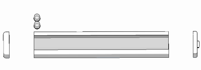
I called the 4 pieces End1, End2, Shell and Bulbs (this is a group with 2 light bulbs)
2. Constraining Geometry
Since this is a component we want to stretch, we want to constrain how it can be stretched. (We want to allow stretching along the Red (X) axis, but not along the green or blue.
This is done by adding Dynamic Component attributes to the whole component, and placing an equals sign in front of the Y and Z sizes.
A. Select the main component, right click and select: "Dynamic Components/Component Atributes"
(This is only available in SketchUp Pro)B. At the top of the attributes list, will be the main component. Select "Add Attributes", and select LenY and LenZ (we will need LenX later, so you might as well add it as well.)
C. To constrain an attribute, (which means the user cannot change it - even while stretching the component), click on it twice, until the text turns black and the background turns white, then place an equals sign in front of it and hit enter.
This "freezes" the value of that attribute so it cannot be changed.
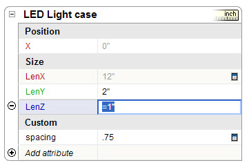
D. "Freeze" LenY and LenZ, but leave LenX changeable (it will show as grey rather than black)
3. Calculate lengths and positions of pieces.
This part can be tricky, but fortunately the Dynamic Components system shows you what is happening as you change things which makes it a little easier.
Basically, everything is based on the length of the component after it is stretched. This is the LenX attribute we added earlier but did not change. This is called "LED Light case!LenX", where "LED Light case" is the name of my component. "!LenX" means to get the X length of the entire component.
For my example, the two end pieces are 0.5" long. This means the length of the center piece ("Shell") is the length of the whole component less 1" (2 x 0.5"). Similarly the X location of the End pieces and the shell piece are calculated from the length of the whole component.
Using similar logic, I added attributes LenX (length) and X (x position) for each of the three pieces which move and stretch with the component.
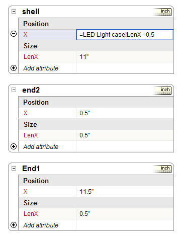
A. To fix the length of the end peices, double click on Lenx, and enter the fixed value (=0.5")
B. To set the variable length of the Shell, double click on LenX, then enter =, then point to the LenX field of the main component, that will add "LED Light case!LenX" to the value, then type in "-1" and the end to subtrace then lengths of the end pieces. The whold thing should look like: =LED Light case!LenX - 2
C. The X positions of the three pieces are similar.
X for End1 should be 0 (starts at 0)
X for the Shell should 0.5 (start 1/2 inch in - past end 1)
X for End2 should be =LED Light case!LenX - 0.5 (starts 1/2 inch from far end)These values depend on the origin (axis) locations for the three groups. You may have to reset their axes, or changes these values, depending on how the groups are actually created.
4. making the bulb repeat and fill the length of the component
If you succeed at this, then you are well on your way to becoming a dynamic component maker.
I added an attribute called spacing to the main component, and set it to 0.75". This is the spacing between the bulbs. The user will be allowed to change it later.
Number of bulbs = (total length - length of end pieces) / spacing
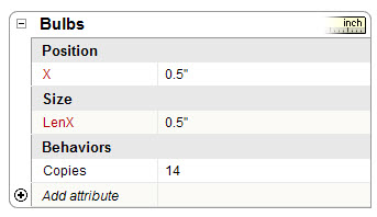
A. Add an attribute to the bulb called Copies (it shows as 14 here, but the actual value is: =(LED Light case!LenX-1.5)/LED Light case!spacing) (This causes 14 copies of the bulb group to be placed - but they are all in the same X location. We will fix that in "C" below)
B. Add the LenX attributes and constrain it to =0.5" - the size of the bulbs
C. Add the X attribute. This is now calulated seperately for each bulb. There is a dummmy attribute called COPY which varies with each bulb number. The value entered into the X attribute field is: =.5 + COPY*LED Light case!spacing
This means that the first bulb (COPY = 1) is placed 1.25 inches from the end of the end f the component (0.5 + spacing which is 0.75), and the second bulb, (COPY = 2) is placed 0.75" further along X. (spacing = 0.75)
5. Other things
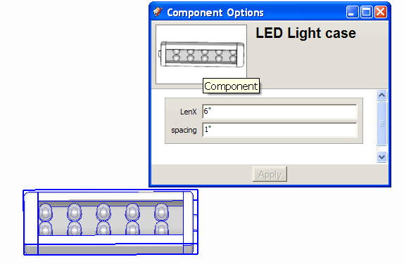
I wanted to let the user change the value of spacing, so on the spacing attribute of the "LED Light Case", you click on the icon o the right which lets you specify that the user can change the attribute, and that it should be displayed in model units.
I did the same for the LenX attribute of the component. This lets the user type in the desired length, rather than using the Stretch Tool.
Here I right clicked on the component, and selected "Dynamic Components/Component Options" to change the length and spacing of the component. Notice that the component was stretched properly, and the number of lights recalculated properly.
6. completed component
I uploaded the component to the 3D warehouse. It may be easier to download it and play with it, rather than trying to make one on your own the first time.
Advertisement


